Pump Alignments
We all know that proper alignments between the pump and the driver are critical. Did you know that the bearing load increases in direct proportion with the misalignment? But even more importantly, a bearing load increase will decrease the bearing life by a cubic function. Simply stated, if the bearing load increases by a factor of two, due to misalignment, then the bearing life decreases by a factor of eight.
Warning: All pumps must be final aligned in the field. No matter how precise the alignment from the factory, it will be lost when the unit is shipped and installed.
Baseplates: Flat and Level
Baseplate flatness has become an issue in recent years as customers are looking to simplify installation and alignment and reduce MTBF (mean time between failures), while attempting to also reduce costs.
Most of us understand that the pump baseplate has to be level. The biggest reason for that criterion is the oil level in the bearing housing. It is possible to have too much oil on one bearing (for example the radial bearing) and not enough on the other bearing (thrust bearing). If the proper oil level is the middle of the bottom ball then it doesn’t take a whole lot of “being un-level” to miss this crucial mark.
What is flat? A typical fabricated steel baseplate for an ANSI or standard industrial pump will be flat to within 0.005 inches (0.127 millimeters) per foot (0.3048 meter).
Example: If the distance between the pump mounting pad and the motor mounting pad is 4 feet (1.2192 meters), then the motor pad can be 0.020 inches (0.508 millimeters) higher or lower than the pump pad. If a pump pad is one foot (0.3048 meter) long, it can be 0.005 inches (0.127 millimeters) lower or higher on one end.
Process Industries Practices (PIP) (and API610) bases for the same model can be 0.002 inches (0.0508 millimeters) per foot (0.3048 meter), or less than half of the standard baseplate. Benefits
A flat surface will allow the installer to more effectively level the baseplate prior to grouting and then align the motor to the pump by shimming under the motor feet. When attempting to align the pump and motor shaft to within 0.002 inches (0.0508 millimeters) TIR (Total Indicator Run-out), it is easier to start out on a level playing field rather than have unequal shim stacks under each foot of the motor.
Extra Credit:
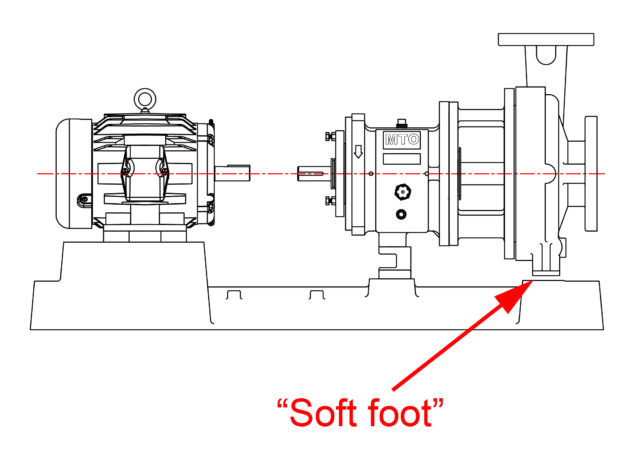
Good millwrights and pump technicians/mechanics know to check for *soft-foot before they start the pump to driver alignment.
*“soft-foot” is where one or more feet are not in contact with the mounting pad when the unit is in the unbolted condition (this should be corrected by shimming, not by tightening the bolt which may distort the motor frame).
If you had a soft-foot of 0.016” and then bolted the motor down anyway; you have just introduced 0.008” of strain/stress into the driver. There is now potentially 0.008” of offset between the front and rear bearings, regardless of the motor size. If you do a similar offset to the pump, again you have introduced an internal stress on the bearings and shaft. Even without soft-foot on either pump or motor, if the baseplate is not flat, you have just done the same thing to the driver and or motor. Bases must be level and flat.
Once a year I attempt to remind all Summit Pump distributors of the “Plug and Play” myths
that unfortunately persist in the pump universe, like fake moon landings and that the earth is flat.
Please make sure you and others on your staff know these 5 key points:
1) OIL: A Pump shipped from the factory does NOT have oil in the bearing housing.
Someone at the pump system site must set the proper amount of the proper oil prior to startup. It is a violation of several federal laws to ship oil in the pump, as oil is considered a hazardous substance.
2) IMPELLER clearance: Final impeller clearance must be set prior to startup. The factory sets the clearance at a nominal setting for the pump type and size, based on ambient temperature liquids, as the factory does not know the specific fluid temperatures or properties
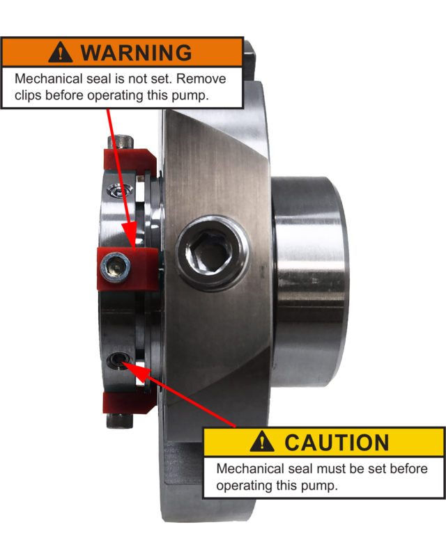
3) MECHANICAL SEAL: A pump shipped from the factory does NOT have the mechanical seal set, in hopes of preventing damage to the sealing faces.
The seal should be set only after adjusting impeller clearance, pump alignment, and rotational checks have been completed
4) ROTATIONAL DIRECTION: A pump shipped from the factory will NOT have the coupling spacer installed because you must first complete the driver rotational check. Additionally having the coupling removed helps in the process to set the impeller and seal. We have a 50% chance of guessing your local electrical phase rotation. If we are wrong, the pump becomes scrap metal.
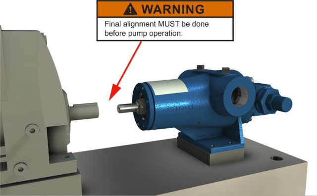
5) ALIGNMENT: A pump shipped from the factory will NOT be precisely aligned to the driver. The factory conducts/logs a rough alignment check during Assembly.
Even if we precision laser aligned the driver to the pump in accordance with NASA and USA Space Force standards, the very Nano-second the skid is picked up by a forklift or other device that alignment will disappear.
Note, that industry best practices (*1) dictate that a driver to pump alignment be checked/adjusted at least 5 times prior to startup. If you don’t know or are unsure about these 5 alignment stages, please check with your Regional Sales Manager.
Summary
A warning tag is attached to each pump to communicate these 5 key steps to the end user/installer. Of course these steps have always been stated in the IOM. The IOM is included with every pump, and can also be downloaded from our website in at least 5 languages.Retort / Conclusion
Several people have retorted that the competition does these 5 things and so their pumps are “plug and play”.I have checked with several knowledgeable and key sources at these competitive firms and that URBAN MYTH is simply NOT true.
As a matter of fact, the other OEMs state they have the same errors / issues with their end users not heeding the warnings on installation and startup.
Exceptions: I will venture to state that perhaps some distributors may offer these 5 key steps as part of their value package. If you do then you are best in class and get a gold star.
More than a minute… Extra Credit Post Script: On a recurring basis we have people rotate ANSI pumps backwards, consequently that trips the motor on overload. Why? Because the impeller will unscrew and “mate” with the casing. The operator subsequently corrects the directional issue (phase rotation), but does not disassemble the pump to check and correct the resultant damage.
Please note that if the impeller has “mated” with the casing there is a very high probability (99%) that the impeller will require replacement, repair and or rebalance, the casing will also require repair, and the shaft is now bent beyond specification, further the bearings and mechanical seal have been mechanically shocked.
Rotation in the wrong direction is a costly mistake.
In addition to my monthly column “Common Pumping Mistakes” the Pumps & Systems editors have asked me to write an article on the common ways that the systems can also reach out and bite you.
If you own a home, a car or for that matter any machine—from a lawn mower to a dishwasher—you already know that all things left to themselves never get better. It is a law of our universe captured eloquently by the word entropy (for the engineers I am using a loose second definition).
For those of you that already own, operate or maintain a mechanical, pneumatic, steam, hydraulic or electrical system, you carry all the battle scars from these real life lessons. As a review for those that already know and as a primer for those that are new to this area, I offer in no particular order, some discourse on the subject.
Your system responsibility—whether a building with HVAC systems, a power plant, a chemical processing or manufacturing facility, a paper mill, a brewery/distillery, wastewater treatment or a manufacturing center—is comprised of machinery: electrical, mechanical, steam, pneumatic and hydraulic. Every system and component has a finite life.
Machinery Fails
All machinery, operating or idle, will eventually fail. Machinery fails for the following basic reasons: corrosion, erosion, stress or impact. Your job is to prevent it from failing or failing at the wrong time. When the machine does fail, we hope to manage it in a predictable and safe manner.
Ask yourself if you and your staff have the proper training and equipment for flash protection, confined entry, general electrical safety, chemical handling, radiation exposure, noise, noxious/carcinogenic or poisonous gases, safety chains, ladders, rigging/lifting equipment, signage, rotating machinery and OSHA guards.
Education/training in all of these areas is very important. Additionally, consider whether the current training is adequate for new personnel or is simply a review of procedures for the seasoned employee. Note that most injuries occur during non-routine or emergency evolutions.
Manage by Walking Around
If you do not manage the system, it will manage you. Choose a new system every day and grab the system logic process diagram for review. Do you really know how the system operates? If you do not know how the system operates, you will not know if anything is wrong until it is too late. So, the prudent thing to do is learn the system. With a flashlight, rag, clipboard and a camera, walk and trace the system “hand over hand” to look for issues and changes.
Look for leaks, wear, erosion, corrosion, abrasion and discoloration. Look for unauthorized additions and alterations. Use all of your senses including smell and hearing. Look for what has changed in the system operation, starting with different pressures, flows or levels. Check and review system logs for long-term trends.
Most plant issues occur when there is a change in the status quo.
Heat Exchangers
The biggest “corrupter” of heat exchangers is fouling and corrosion. (From a dictionary aspect, corrupter is not the correct word choice to describe the issue, but I insist in this case it is appropriate). Both fouling and corrosion lead to a reduction in performance, and in some cases to erosion with consequential and undesired leaks. Determine the exchanger performance or heat balance by measuring the flows, differential pressures and temperatures on both sides of the unit. Compare readings and thermal balance results to prerecorded, new or clean parameters. Heat exchanger maintenance or replacement is time consuming and costly, so do not wait for catastrophic failures when a few simple checks can help you predict the need for repair or replacement.
Because my heat exchanger experience is with nasty fluids at high pressures and temperatures, I have a prejudice for shell and tube exchangers. I am also aware that plate and frame exchangers offer many advantages and that the newer designs have improved capabilities and reliability.
On shell and tube type exchangers, the tubes can plug from the process fouling, corrosion or debris. From past tube failures, there may also be tubes that are manually plugged and taken out of service. An accepted common industry maximum level of tube plugging is 10 percent, but I caution users to always consult the manufacturer since some designs will demand a lower percentage. According to Tubular Exchanger Manufacturer Association (TEMA), the acceptance level for “U” tube designs is only 1 percent. Whatever the acceptable range is, at some point plugged tubes will need to be replaced or the heat exchanger performance derated. You can also clean the tubes and shell side as a maintenance procedure.
Plate and frame heat exchangers are less susceptible to fouling due to designs that yield higher fluid velocities and turbulence in the channels. Plate and frames are also easier to clean, maintain and change performance dynamics. My caution to personnel adding, changing or cleaning plates is to be very careful of the plate orientation and design. The most common issue I witness is how easy it is for plates to be installed incorrectly—in the wrong order or the wrong plate altogether. The other issue is with gasket leaks due to inadequate torque or mishandling.
Valves
Control and throttling valves have exposed trim, stems and seats that will wear and corrode, which not only changes the pressure drop across the valve, but pieces of the valve/trim will lodge in downstream machinery. Another issue is with zealous mechanics that tighten the packing so tight the valve actuator cannot develop sufficient torque to operate the valve. The end result is a system not operating properly and the expensive actuator destroyed.
Note that proportional programmable logic control (PLC) valves will drift and the settings will change with time, temperature and vibration. When was the last time the valve settings were checked?
Foot valves in the suction line of self-priming pumps will become jammed open or closed with debris, destroying an expensive pump and then causing a loss of service. Other styles of non-return valves/check valves can fail or wear, allowing process flow to reverse direction. Pumps running in reverse are a common cause of broken shafts. How often do you check that your non-return valves are working and the spring factors are correct?
Strainers
The first two universal laws are that; 1) concrete will crack and 2) flat roofs will leak. The third law is that strainers will clog and starve the downstream equipment, typically a pump. I am simply amazed by the number of strainers I observe with no means of determining the differential pressure. A simple inexpensive duplex gauge will indicate when the strainer is clogged and can save thousands of dollars.
Motors (Electrical)
Overloaded induction motors draw high amps that force the motor to operate above nameplate temperatures. This condition will rapidly degrade the insulation and the motor will burn out. The quality and integrity of the power supply such as voltage excursions and issues with blocked ventilation or frequent starts and stops will also affect the insulation life. As a general rule of thumb, insulation life doubles for each 10 C of unused insulation temperature capability.
Operators/owners that believe it is perfectly acceptable to operate motors in the service factor range will quickly become the favorite annuity for the motor sales people. You can easily and safely determine your operating motor stator temperature with an infrared thermometer.
There are several motor health tests that can easily be conducted such as electrical resistance (Ohm resistance between phase legs), insulation resistance (megger test), running amps and voltage. Perhaps better left to trained technicians for more in-depth testing are surge frequency and partial discharge tests. Several companies offer motor analyzers and training.
Note that some technicians consider the megger test as a potentially destructive test. Depending on the voltage level used, you can possibly force a failure of the insulation system.
Motors (Hydraulic)
Hydraulic motors, if operated in the proper pressure and temperature range with clean fluid will perform very well for a long time. Like everything else in a hydraulic system cleanliness is paramount. I cannot overstress this point. These systems will run reliably for a long time as long as the oil is clean and cool. An abundance of caution is required to keep all dirt and contamination from the system.
Motors (Pneumatic)
Air motors will perform well if the air quality is consistent to the motor design requirements. The air supply to the motor must be clean and dry which means filters and moisture separators must be maintained properly. Additionally the lubricators that are critical for motor efficiency and long life (prevent corrosion) must be in working order with an adequate supply of the correct oil.
Transformers
No matter if it is a small dry insulated 1 kilovolt or a large 1,000 megavolt FOA (forced oil and air) cooled transformer, the insulation will degrade consistent with age and loading. Power factor and insulation resistance tests can be conducted to determine insulation integrity and life assessment. Oil cooled units must have an oil analysis conducted on a regular basis for water and gases (gases such as carbon monoxide and carbon dioxide, hydrogen, oxygen and methane). You need to be especially concerned with the combustible gases acetylene, hydrogen and methane as these are indicators of a serious condition called corona (arching and short circuiting in the windings) and will, if left unfettered, lead to catastrophic failure.
Batteries
What good is an emergency system if it does not work in an emergency? Battery backups for ancillary and tertiary uninterrupted power supplies (UPS) and direct current (DC) controls must be in a fully charged and ready condition. Batteries of all technologies, but especially lead acid types, have well defined life spans that are severely shortened if not maintained properly. Specific gravity and fluid levels must be correct. Dead cells need to be bypassed. Amps draws should be periodically checked and corrosion on connections cleaned and addressed. Most lead acid batteries should have a specific gravity of 1.265 to 1.280 at an ambient temperature of 78 F.
Electrical
Taking full safety precautions and certified training—inspect electrical enclosures, conductors and terminals for tightness, discoloration and heat using infrared technologies. Aluminum connectors are a special consideration and must be checked for proper torque and treated for oxidation on a periodic basis. Aluminum conductor terminals will loosen with time due to the heating and cooling cycles associated with loading and unloading. This cycle of expansion and contraction will cause the connection to loosen and will subsequently require re-torqueing.
Many of the older breakers contain asbestos arc chutes. Asbestos is the best material to handle the extremely intense heat of arc interruption but presents other carcinogenic problems when handled during maintenance.
SF6 (sulfur hexafluoride) gas is found in many of the higher voltage breakers because of its unique and inherent dielectric properties. SF6 is a colorless, odorless, tasteless and nontoxic heavy gas. The danger of SF6 gas is that it displaces oxygen (air), and therefore can potentially cause suffocation. From an environmental perspective, it is potentially a very dangerous greenhouse gas, but because it is so heavy compared to air (does not naturally rise to high altitudes like Freon) and is confined to pressured spaces, any deleterious effect is minimized.
Compressors (Air)
If you have one or more high horsepower compressors (greater than 150 hp) operating around the clock, then you already know that the cleanliness of the air intake filters is critical and the unloader and dryer maintenance is essential. For the smaller systems that operate some fraction of the time the receiver tank must be (manual or auto) drained daily, the filters and the oil changed regularly. The most common issue after moisture elimination and air quality is a lack of oil changes. If the compressor operates around the clock, that is 8,760 hours for the year. If you drove your car at 60 miles per hour (mph) for the same amount of time, that equals 525,600 miles (262,800 if you drove at 30 mph). How often would you change the oil in your car for that mileage?
Compressed air is—with rare exceptions—the most expensive utility you have in the plant. Hire a consultant to conduct an air (leak) audit. You will be surprised how much money is being wasted.
Pumps
Since my monthly column is on pumps, I simply suggest you look over my articles of the last 3 years that can be accessed on the Pumps and Systems webpage.
Probably the most important issue I see in the field is that operators do not know where the pump is operating on the pump performance curve. The second and a compounding issue is little to no knowledge of the system curve. The intersection of the system curve and the pump curve is where the pump will operate.
In general, 90 percent of all pump problems are on the suction side of the pump. You should think of the system as three separate systems: the suction system, the pump itself and the discharge system. It is the responsibility of the suction system to deliver the fluid to the pump. It is not the responsibility of the pump to reach out and pull the fluid to the pump, since that is not possible.
Instrumentation & Data Acquisition
Data acquisition systems often translate to imply data overload by an exponential factor. Consequently, the task is to sort through the morass of data and figure what is important and what is not. Data needs to be translated into useful information to be of any tangible benefit. You may require professional assistance to get started. Do not be afraid to ask, and there are several companies that will train you or subcontract the task.
Instrumentation and controls: if you have them, be glad you do. Of course these systems require calibration and maintenance just as the main systems they manage. If left to themselves, they will also drift and fall out of calibration.
Gauge calibration programs are paramount, and yet I see few plants that have gauges in most systems. If they do have gauges, there is no system to maintain or calibrate the instruments. Standard type gauges will drift over time due to bourdon tube stress, spring vitality, vibration and shock. There are alternatives to gauges such as pressure transducers and there are safe remedies for those other nasty locations. If you do not measure it, you cannot manage it. I am constantly amazed by the lack of system parameter measurement at many plants. They have no pressure gages, no flow measurement, no level indication and no temperature indicators and yet will be very upset when their system fails.
Lubrication Systems
Lubrication and the associated system cleanliness are extremely important. Dirt, contamination and water are the biggest killers of ball bearings. Just 250 parts per million of water in the oil will reduce bearing life by a factor of four.
Generators
Generators (standby electrical) need to operate with some periodicity to exercise the unit and check for potential issues. Lubrication must periodically be reintroduced to the bearings and cylinders and condensed moisture in the fuel needs eliminated. When the main power goes out is not the time to test the generator. One interesting issue I commonly run into when troubleshooting generators is that the frequency settings will be set for 50 hertz on a 60 hertz system. The other issues are lack of coolant or coolant quality, failed block heaters and bad fuel.
Conclusion
These are simple and basic tips to help you manage your systems. If this article is of interest to the readers we can discuss in future articles a host of other subjects that did not fit into this one, such as: steam turbines, steam traps, fans, blowers, vacuum pumps, vibration analysis, freeze damage, heat trace (electric or steam), freeze protection, couplings, belts, sheaves, drive chains, gaskets, O Rings, elastomers and conveyors.
Ask a few questions about recent changes.
Did the operator change?
Was the system worked on, and if so what was the job scope?
Was the scheduled maintenance was actually performed, performed correctly and documented?
From an outsourcing perspective, did your company change vendors, suppliers or technicians?
Jim Elsey helps you avoid common centrifugal pump mistakes.
I have been writing “Common Pumping Mistakes” for Pumps & Systems for more than three years. Typically the hardest part of the job is topic selection so it will be fresh, educational and interesting. This month, I am writing on a collection of shorter subjects and baking them up into one article. Instead of a meal, we will have hors d’oeuvres. Hopefully it will satisfy your appetite. If you have been reading my column, many of these tidbits will be a review. These comments are based on single-stage overhung centrifugal pumps moving ambient temperature clear water, except when otherwise noted.
Pumps are really designed to operate at only one point. That hydraulic condition of one point of head and flow is the best efficiency point (BEP), also known as the best operating point. Anywhere else on the published set of curves is simply a commercial compromise. It would be too expensive for most end users to have a pump designed and built for their unique set of hydraulic conditions.
Pay attention to the published pump curves. Manufacturers’ pump performance curves are based on clear water at approximately 65 F, unless stated otherwise. They will not be corrected for fluid viscosity. The horsepower stated may or may not be corrected for specific gravity or viscosity.
When the manufacturers’ published pump curve stops at some point of flow and head, it is for a good reason. Do not operate the pump at the end of the curve; if there was more performance to be generated from the curve beyond that point, the manufacturer would have extended the curve. Operating at or near the end of the curve will be fraught with performance issues.
Pumps are stupid. A centrifugal pump is simply a machine, where for a given set of fluid properties, impeller geometry and operating speed it will react to the system in which it is installed. The pump will operate (flow and head) where its performance curve intersects the system curve. The system curve dictates where the pump will operate.
Understand the system curve. The system curve represents all of the friction, static and pressure head baked into the system. Velocity head is also present, but typically too small of a component to be concerned about.
Pumps do not suck fluids. This is a common misunderstanding, but realize that some energy source other than the pump must supply the energy required for the fluid to get to the pump. Normally these are gravity and/or atmospheric pressure. Lastly, fluids do not have tensile strength. Consequently the pump cannot reach out and pull fluid into the suction.
The maximum realistic suction lift is about 26 feet. See the previous section where pumps do not suck. If you are at sea level the atmospheric pressure will be 14.7 pound per square inch absolute (psia), which translates (multiply by 2.31) into about 33.9 feet of absolute head. So, in a perfect world, if there was no fluid friction or vapor pressure working against the system you might be able to lift cold water 33 feet.
In reality, fluid friction and the negative consequences of vapor pressure will work against you and preclude fluid lifts of much more than 26 feet. Always calculate the net positive suction head available (NPSHA) and compare to the pump’s net positive suction head required (NPSHr) value. The higher the margin, the better.
A pump running backwards does not reverse the flow direction. The flow will still go in the suction and exit from the discharge nozzle. Depending on the specific speed (Ns) of the pump (think impeller geometry), the flow and head will be reduced by some significant amount because the pump is much less efficient. For lower specific speed pumps the flow will be approximately 50 percent of rated and the head will be 60 percent of rated. An American National Standards Institute (ANSI) pump running backwards will cause the impeller to unscrew from the shaft and lodge itself in the casing.
You cannot vent air from the impeller eye of an operating pump. A pump is in many ways like a centrifuge, and so the heavier water is expelled to the outside diameter and the lighter air remains in the middle or center. The pump should be at rest to be properly vented. Pumps with centerline discharges are essentially self-venting.
Industrial pumps do not come from the factory ready to “plug and play.” There are exceptions to this comment, but never assume. The pump will require oil to be added to the bearing housings. The impeller clearance must be ascertained and set for the fluid (temperature) to be pumped. The driver will need to be aligned to the pump. Yes, the alignment may have been performed in the factory, but the second the unit was moved for transport the alignment was lost.
You will need to check alignment again after the piping is installed, and again when the base is grouted in. The direction of rotation should be ascertained and matched to the phase rotation on the motor driver.
The mechanical seal will need to be set after these other steps are completed. Most manufacturers do not install the coupling at the factory because it will just need to be removed for all of these aforementioned reasons.
Almost all pump problems occur on the suction side. There is a common and pervasive misunderstanding about how pumps work. Refer to above as a reference. Think of any pump system as three separate systems when trouble shooting issues in the field. The suction system, the pump itself and the system downstream of the pump. In my years of working on pumps and solving issues, 85 percent of pump issues occur on the suction side. When in doubt, it is a great place to start looking for the solution.
Always, always, always calculate the NPSHA. This is likely the most common and the most expensive mistake I witness in the field. People will erroneously think that because they have plenty of suction pressure or a flooded suction there is no reason to do these calculations. A few feet of friction or additional losses due to vapor pressure can wipe out that NPSH margin you thought you had. Insufficient NPSHA will result in cavitation in the pump impeller.
NPSHr has nothing to do with the system and is determined by the pump manufacturer. NPSHA has nothing to do with the pump and should be determined or calculated by the system owner or end user. I recently heard a phrase that the “pump becomes grumpy and grouchy” when there is an insufficient NPSH margin.
Understand cavitation. Cavitation is the formation of vapor bubbles in the fluid stream due to a drop below the vapor pressure of the fluid. The formation of the bubbles typically occurs just in front of the impeller eye since this is typically the lowest pressure in the system. The bubbles subsequently collapse downstream as they enter a region of higher pressure. The bubble collapse is what causes the damage to the pump impeller.
Cavitation causes damage. If the bubbles collapse in the middle of the fluid stream there is almost no damage. But when the bubbles collapse near or at the metal surface, they collapse asymmetrically and cause a small microjet. This collapse occurs on a nanoscale (1.0 x 10⁻⁹ or billionth). Local pressure forces involved can be higher than 10,000 pounds per square inch gauge (psig) (689 bar) or more, plus there is heat generated. This phenomenon can occur at frequencies up to 300 times per second and at speeds near the speed of sound. Note the speed of sound in air is approximately 768 miles per hour (mph) (1,236 kilometers per hour [k/h]) and varies somewhat with humidity levels. The speed of sound in water is 4.4 times faster at about 3,350 mph (5,391 k/h or 1,490 meters per second [m/s]). Because I started my career in the submarine world, I have to point out that the speed of sound is even faster in salt water.
Cavitation damage can occur at different locations on the impeller. “Classic” cavitation damage will occur approximately one-third of the distance downstream of the eye on the underside (low pressure side or the concave side) of the impeller vane. “Classic” because it is due to insufficient NPSHr. Cavitation damage may manifest at other locations on the impeller, but those instances usually are due to recirculation issues that are caused by operating the pump away from its design or BEP.
Cavitation is audible in the lower ranges. If you hear the cavitation noise (sounds like pumping gravel), it is likely cavitating. Just because you don’t hear the noise means nothing, since the majority of the noise range is outside the range of human hearing. Perhaps we should train dogs to help us detect cavitation? Cold water is typically the worst fluid for the consequential damage from cavitation.
Hydrocarbons have minimal effect from a damage aspect. Hydrocarbon correction factors exist and are based on empirical data. The rules for correction factors are covered in the Cameron Hydraulic Data book.
NPSHr is NPSH3. When a manufacturer states that the pump requires a certain amount of NPSHr at a given point, realize that the pump is already cavitating at that point with a 3 percent head drop because that is how NPSHr is measured. All the more reason to assure you have adequate margin.
Critical submergence is necessary to prevent vortexing. The vertical distance from the surface of the fluid to the pump inlet is the submergence level. The distance required to preclude air ingestion due to vortexing is the critical submergence level.
To preclude the ingestion of air, do not operate the pump when the fluid level is below the critical submergence. The vortexing phenomena is a direct function of the fluid velocity. You can preclude vortexing by the use of baffles and/or larger pipe diameters such as bell flanged inlets. There are numerous reference charts on submergence to use when looking at the suction side design. The best one would be from the Hydraulic Institute. A conservative rule of thumb is to have one foot of submergence per foot of fluid velocity.
Pumps cannot efficiently move fluids mixed with air if the percentage is greater than 4 or 5 percent. Most pumps start to lose performance around 2 to 3 percent air entrainment. Almost all pump designs will cease to perform at around 14 percent entrainment. Exceptions can be disc pumps, self-primers and some vortex or recessed impeller type pumps.
My pump bearing feels hot. This is a common comment, but it is subjective, not objective. It is difficult for the typical person to hold their hand on a bearing housing that is over 120 F.
It is perfectly normal for a bearing to be operating at 160 to 180 F. Use a thermometer or infrared device to measure the temperature and deal in facts.
Viscosity is the kryptonite of centrifugal pumps. Most centrifugal pumps become too inefficient or exceed their horsepower (hp) limits in a viscosity range between 400 and 700 centipoise that depends on pump size. Always check with the manufacturer when pumping viscous fluids for corrected curves and power limits for the frame, bearings and shaft.
Horsepower requirements progressing along the pump curve change for different impeller geometries. Low and medium specific speed pumps require more hp the farther out on the curve you operate, which is fairly intuitive reasoning. For high specific speed pumps (axial flow), the highest hp required will be at the lower flows. This is also why it is common to start up these types of pumps with the discharge valve open so as to not overload the driver.
There is a simple way to think of specific speed. Specific speed (Ns) is a tool used by designers to look at the performance and geometry of a hypothetical impeller. Don’t want to get all caught up in the math involved? A low specific speed impeller will have the flow enter parallel to the shaft centerline and leave the impeller at 90 degrees to the centerline. A medium specific speed impeller will enter parallel to the shaft and exit the impeller at 45 degrees to the centerline.
A high specific speed impeller will operate with the flow entering parallel to the shaft centerline and leave parallel to the centerline.
Some people still think they can align a pump with a straight-edge, in lieu of a laser or dial-indicator method. They are incorrect. While a straight-edge alignment can potentially kill your bearings, seals and couplings, it also consumes extra horsepower.
Recent studies show that a simple 0.050” offset, which is about the best straight-edge alignment possible, will consume 9% more power. An angular misalignment of 0.015” gap per inch of shaft diameter will consume 6% more power.
At least once a month, we will receive a complaint that our pump is not aligned to the driver upon site arrival. We try to advise our distributors that the final alignment must be performed in the field. An initial rough alignment is done at the factory to prove that the unit is able to be aligned, but as the pump is transported, the unit will become out of alignment. Pump units should be alignment checked five different times during the course of the installation. (We will cover that subject another time.)
Also, note on existing installations you would never move the pump, only the driver. Although, on new installations before the piping is brought to the pump, it is perfectly acceptable and sometimes necessary to move the pump within the room allowed by the bolt holes.
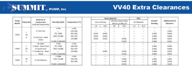
Did you know that when using an internal gear pump in applications above 225 degrees Fahrenheit or viscosities above 750 SSU, the pump may need extra clearances to operate properly? These extra clearances are applied to the rotor’s outer diameter, rotor’s inner diameter, the end clearance and (if applicable) the shaft or bracket bushing inner diameter.
In high temperature applications, the extra clearances are needed to allow for expansion of the materials. As a manufacturer, calculations for the clearances are controlled by material selections and are determined based upon a specific material combination within the pump. Changing the part’s materials could change the amount of extra clearances needed for the pump.
High viscosity applications need the extra clearance to allow the fluid to pass through which keeps the pump from reaching its maximum allowable horsepower limit. If these clearances where not applied, excessive wear or failure of the pump would be premature.
This is just one reason why it is of the utmost importance to collect the application’s fluid and process properties to keep your pump’s life at a maximum.
 Once a year I attempt to remind all Summit Pump distributors of the “Plug and Play” myths
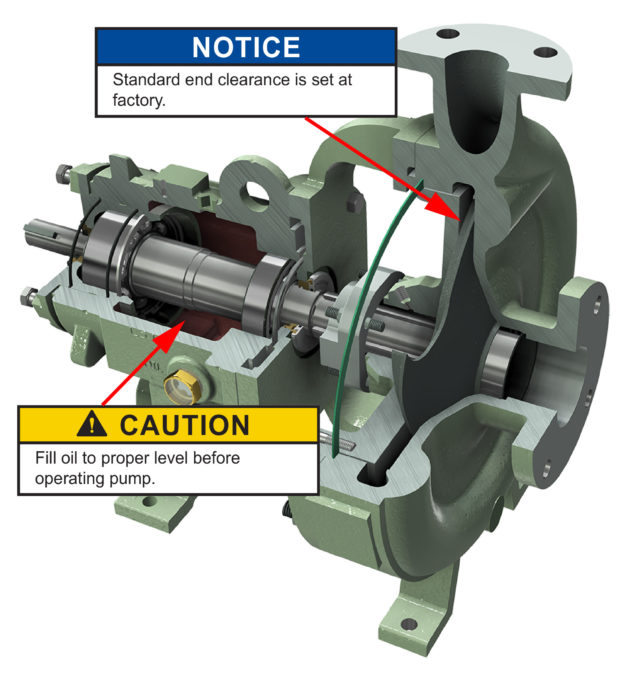
 Retort / Conclusion
 Some people still think they can align a pump with a straight-edge, in lieu of a laser or dial-indicator method. They are incorrect. While a straight-edge alignment can potentially kill your bearings, seals and couplings, it also consumes extra horsepower.
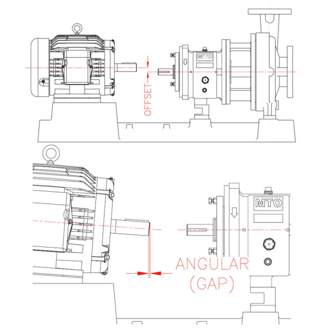
 Did you know that when using an internal gear pump in applications above 225 degrees Fahrenheit or viscosities above 750 SSU, the pump may need extra clearances to operate properly? These extra clearances are applied to the rotor’s outer diameter, rotor’s inner diameter, the end clearance and (if applicable) the shaft or bracket bushing inner diameter.
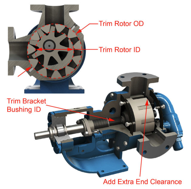 In high temperature applications, the extra clearances are needed to allow for expansion of the materials. As a manufacturer, calculations for the clearances are controlled by material selections and are determined based upon a specific material combination within the pump. Changing the part’s materials could change the amount of extra clearances needed for the pump.