Resources, Summit Pumps
 Imagine if you will…
You are a conscientious pump technician/owner/operator. You have a strong passion to properly care for the pumps under your safekeeping… your goal is to attain the highest possible level of machine reliability. You do all of the right things to maximize and extend the run time between failures. You want to be the best in the industry.
What Killed my Pump?
Ironically, after completing a list of best practices for your pump it will die a short time after you commission the system. Why? Because what you didn’t plan for was the elimination of simple pipe strain.
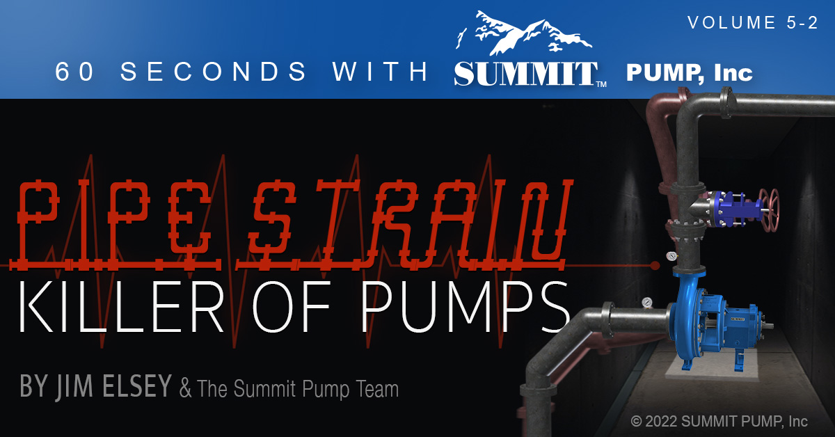
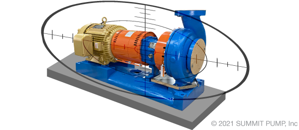
Pipe strain is the misalignment of suction and discharge piping in relation to the pump. Resulting forces are transferred into the pump, stressing internal components, degrading alignment, and ultimately causing premature equipment failure. Ideally, no external force should be required when aligning pipe flanges.
However, while you were busy working on another project, the group that installed the pump used a 10-foot pry bar, three come-alongs, one hoist motor, two mules and some heavy chains to persuade the already installed piping* to matchup and bolt to the pump flanges. If you could remove the bound flange bolts at this point (that are wedged in due to strain) the pipe would likely swing wildly two feet away from the pump flange.
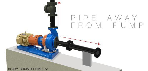
*Note: You should always pipe away from the pump, not to the pump.
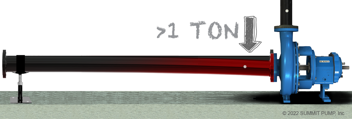
Example 1: Incorrect Pipe Fitting
An 8-inch suction line of schedule 40 steel. The line is supported approximately 6 to 7 feet away from the pump. A simple quarter inch of parallel offset at the flange (0.250”) will result in well over a ton (? 2000 lbs.) of force at the pump flange.
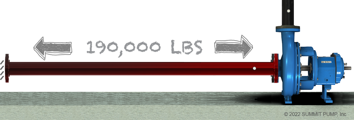
Example 2: Thermal Expansion
A 100-foot run of 6-inch schedule 40 steel pipe will expand over 1.50 inches when heated from ambient to around 200 degrees F. The force exerted on the pump flange would be close to 190,000 lbs. if left unrestrained.
Sum and Substance
Pump internals are not designed to operate within the environmental forces associated with pipe strain. Leaving out the formulas and stress calculations for simplification… with excess pipe strain the centerline of each bearing is no longer congruent to the other so the shaft does not run true. Further, the shape of each bearing is no longer round, the stress has made it eccentric.
Remember, the most expensive pipe anchor you could ever purchase is a pump.
Resources, Summit Pumps
 In the spirit of continuous improvement we like to occasionally remind our readers about important factors that are essential for a successful pump installation. Liquid properties such as viscosity has relatively little effect on positive displacement pump performance and in most cases makes them even more efficient, but viscosity is pure kryptonite for centrifugal (rotodynamic) pumps.
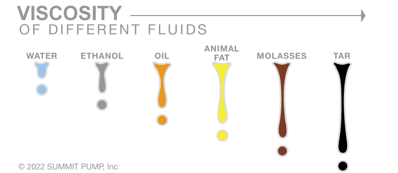
What is Viscosity?
Viscosity is that property of a fluid which tends to resist a shearing force. Simply stated; does it pour fast or slow …or how quick will a ball bearing fall through a vertical column of the liquid? You may also think of viscosity as the internal friction resulting when one layer of the fluid is made to move in relation to another layer. The viscosity of liquids will decrease as the temperature increases which is the opposite characteristic of gases.
Curve Corrections
Centrifugal pump published performance curves are based on water and so when moving viscous fluids the performance must be corrected. Technically the pump performance curve should be corrected for viscosities above 5 centipoise (cps) which most people do not do. Please be advised that at viscosities greater than 40 centipoise it is no longer an option and the curve must be corrected. For viscosity corrections we use centipoise units. See Hydraulic Institute/ANSI standard 9.6.7 for more details.
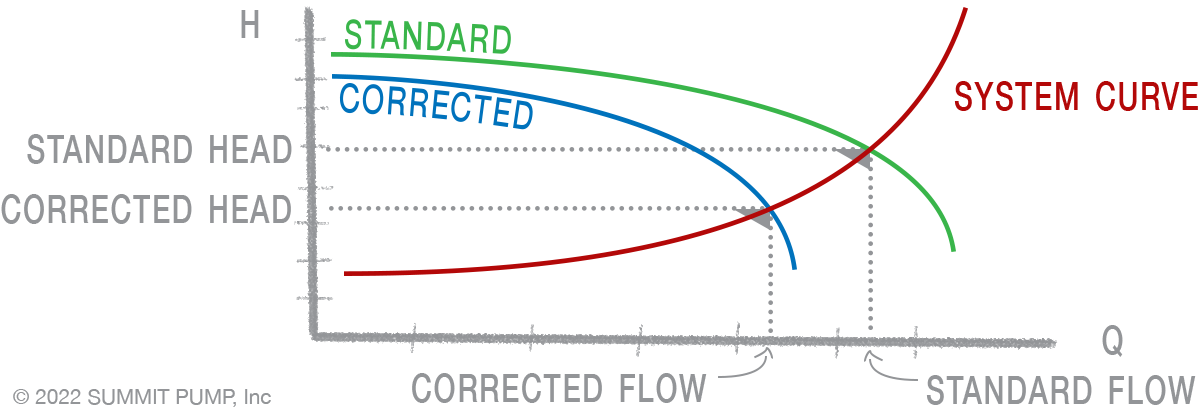
As viscosity increases:
- Pump efficiency will decrease significantly
- Flowrate will decrease
- Developed head will decrease
- Power (bhp) required will increase
- NPSHR will increase and the NPSHA will decrease
- System curve will become more restrictive
- Affinity laws will become inaccurate
Centipoise vs. Centistoke
A simple way to explain the difference between these two terms is that…
Centipoise: Dynamic viscosity is a measurement of the force required to overcome fluid resistance to flow through a tube (or capillary).

Centistoke: kinematic viscosities are timed flow rates through orifices where the driving force is typically gravity.
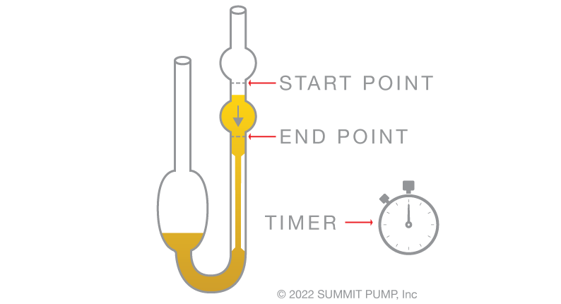
The relationship between Centipoise and Centistokes is proportional via the specific gravity.
Centistoke = Centipoise ÷ Specific Gravity
Pumps Have boundaries
All pumps have limits as to how much horsepower can be utilized. This boundary is based on power frame (shaft and bearing) speed versus torque limits and is normally expressed in BHP per 100 rpm terms.
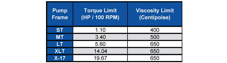
Note: These stated limits are based on direct drive and must be reduced for belt or engine drive. See engineering for assistance.
Maximum Limit: Should you need to pump liquids at higher viscosities please contact us to review the application. Viscosities above 2000 – 2500 centipoise must be handled with positive displacement pumps.
Caution: Do not apply the Affinity Laws directly to viscosity performance corrections. You must first correct the viscous performance to its equivalent water performance before the Affinity Laws are applied. Once you have determined the new water performance then the viscous correction factor can be applied to estimate the new viscous performance.
Good news: All of these required viscosity calculations can be easily accomplished in a few keystrokes on Summit Select.
Resources, Summit Pumps
 Today we will discuss ANSI pumps with a focus on Summit’s model 2196 product line.
Pump Impeller Clearance
When a pump leaves our OEM factory there are a minimum of five critical steps required (to be completed in the field) as part of commissioning and starting up the pump. One of these five key steps is setting and or verifying the impeller clearance.When asked what dimension to set the clearance many individuals will throw out a nominal number like 0.015” and sometimes that is right, but many times it is wrong. And so, it is important to realize that the clearances are different for each size, type and model of pump along with the essential factor of product temperature.
Below is a chart from the 2196 manual as a reference:
Pump Efficiency or… What happens if the clearances are opened up further then the factory recommendations?
In general: Once impeller clearances reach 0.005”- 0.010” in excess of the factory design clearances the efficiency loss will be approximately one to one. That is, there is a one percent efficiency loss for each additional 0.001” of clearance.Once you exceed 0.010” beyond the factory advised clearances the rate changes and it then becomes a two to one loss. That is, there is an additional two percent loss for each additional 0.001” of clearance.
Efficiency continues to decrease dramatically as clearances increase. Once clearances exceed 0.015 to 0.020 over the initial clearance, the rate of efficiency decrease can become exponential, first as a square function and then by the cube and so on. Somewhere in excess of 0.030” to 0.040” the pump loses most of its ability to pump effectively.
What should I do?
Even if you set the clearances correctly at startup… over time, wear on both the casing and impeller will inevitably take place and so the pump will experience a loss of efficiency and performance. At which point, you’ll need to readjust the impeller clearance to compensate for the wear. As a general “thumb rule” once the clearance is doubled from the original settings, the pump clearances need to be reestablished to the original dimensions. Please talk with your RSM for more information on this topic.
Why should I maintain proper pump clearances?
Setting proper impeller clearances on pump installations is a critical and crucial step.
Note that as clearance increases…
Resources, Summit Pumps
One of my previous Pumps & Systems columns expounded on an urban myth that all centrifugal pumps arrive on the jobsite ready to operate—“plug and play.” In almost every case, this myth is “busted.” Most every pump requires at least five areas of attention prior to startup, including setting the impeller clearance, which is the focus of this month’s column.
This example uses the most common type of pump—a B73.1 ANSI pump. Most manufacturers include an instruction manual and warning tag that advise the following information about the startup process:
Alignment: The alignment (driver to pump) as received is probably not correct, and it is surely not the final alignment that would satisfy acceptance criteria. Even if the factory completed an accurate alignment, it will change during the transit and installation phases. When the base is installed on the foundation and the piping is bolted on, the alignment will change.
Bearing housing: There is a 98 percent chance that no oil is in the bearing housing.
Mechanical seal: The mechanical seal is not set to the proper dimension. It may be in a safe (sleeping/transit) position with shipping clips installed. The mechanical seal may not even be installed. These are additional reasons why the coupling is not installed (fully) at the factory.
Phase rotation: Assume the driver is a 3-phase motor and the factory has no data in reference to your electrical system phase rotation. There is a 50-50 chance the factory will have the phase rotation correct. If it is wrong, you risk destroying your new pump.
This is another reason why the coupling is not installed.
Impeller clearance: Last but not least—the focus of this month’s column—is setting the impeller clearance. I continually witness this step ignored or completed improperly more than any of these mentioned issues.
Even if the purchase order specified for the factory to set the impeller clearance at a certain dimension, why would you not check the clearance in the field to verify the setting is correct? Unless there is an unbroken chain of custody with the pump, you cannot be positive and, besides, it is easy to check.
Why do you care if the impeller is set incorrectly? In addition to reduced efficiency, you are effectively reducing the impeller’s size. Just 0.015 to 0.020 inches off the correct clearance can reduce the performance of a 10-inch impeller to perform like 9.5 inches.
There are primarily two main styles of ANSI pump impellers. This article will not address the subsets of low flow/high head (constant velocity) and recessed impeller (vortex) designs.
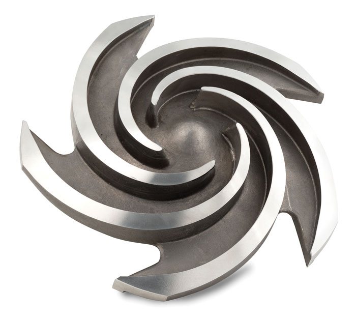
Image 1. A semi-open impeller. (Images and graphics courtesy of the author)
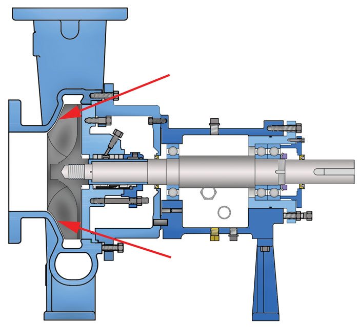
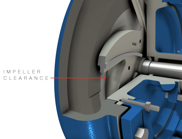
Figure 1. A diagram of a pump with a semi-open impeller, indicated by the red arrows (Images and graphics courtesy of the author)
Impeller Designs
There are two main styles of pump/impeller arrangements: open impeller and reverse-vane impeller.
With an open (semi-open) impeller (see Image 1), the clearance is indicated (set) off of the pump casing to the front side of the impeller (vane tips). With a reverse-vane impeller (see Image 2), the clearance is set off of the stuffing box to the back side of the impeller.
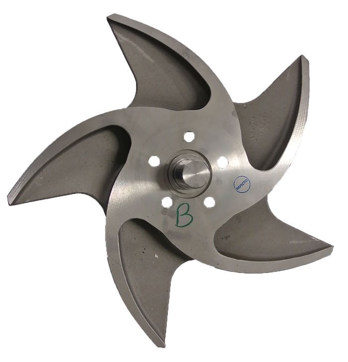
Image 2. A reverse-vane impeller.

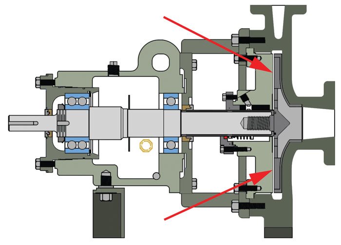
Figure 2. A pump with a reverse-vane impeller, indicated by the red arrows
Both are good designs, but determining which one is better depends on the fluid properties you are pumping and perhaps the hydraulic conditions dictated by the system design. If the question of which design to use was up for debate, I would gladly accept a position on either side.
The concern is that many mechanics do not set the impeller to the proper clearance no matter which style of pump and impeller is used. On either style, the entire rotating assembly (shaft, impeller and bearings) can be moved axially utilizing design features at the coupling end of the pump bearing housing. In both cases, with the pump assembled you can move the impeller (the entire rotating assembly) toward the suction end of the pump until you touch the casing and in the other direction until the impeller touches the stuffing box (sometimes called the sealing chamber or back plate).
The difference is that with open-style impellers the correct running clearance is set off of the casing (see Figure 1), and with reverse-vane impellers the clearance is set off of the stuffing box or back plate (see Figure 2).
The actual impeller clearance dimension will vary by manufacturer, but more so by pump frame size and the temperature of the fluid being pumped. Refer to the manufacturer’s instruction book for the correct clearance based on frame size and temperature.
If using dimensions that are dated—for example, a shop “cheat sheet” posted near the workbench—you will want to update your data. Most manufacturers have closed (reduced) the clearances in recent years as a technique to increase pump efficiency.
The detailed procedure for how to properly set the clearance will be covered in the instruction book. There are usually at least two acceptable methods to accomplish the task. I prefer the dial indicator method because of the accuracy, reliability and validity. As an experienced engineer, I will acquiesce that feeler gauges can work just as well in the hands of a good millwright.
The common mistakes I see when the mechanic sets the clearance incorrectly include: not choosing the correct clearance for the pump size and temperature; setting an open-style impeller to the stuffing box; setting a reverse-vane impeller to the casing (volute); and setting the impeller in the middle of the travel.
Correctly Setting Your Impeller
If rebuilding the pump, always check the following factors prior to setting the impeller:
- Using a dial indicator: Check for runout on the back edge of the impeller shroud. Consult with the manufacturer for acceptable tolerances. On an open-style impeller, one vane tip that is sticking out will yield a false setting clearance and can easily affect the pump performance.
- Rotor travel: Whether a rebuild or a new pump, measure the total travel of the rotor and record that dimension. At a later date (months or years), again measure the total travel without taking the pump apart. The new (larger) dimension compared to the original will reveal how much the impeller vanes and casing (or stuffing box) have worn. It will not show exactly how much on each component, but it will give the amount of total wear. Most manufacturers do not record this dimension when the pump is manufactured. Also, it will be slightly different for every pump due to acceptable and non-critical dimensional tolerances in the castings. Stack and dimensional tolerances will yield the range. Most manufacturers will not give out the drawings/dimensions, but with some prodding they will advise the expected travel range.
- Shipping clips: The mechanical seal should have the shipping clips in place during this procedure. Otherwise, the seal settings will be incorrect and/or the seal faces can be damaged.
- Rotor turning: The rotor should turn freely by hand with no rubs or binding.
- Casing gasket: Use the correct thickness casing gasket or the impeller may be too far or too close to the casing or stuffing box.
- Skim cut: More than once I have witnessed a repair shop take a “cleanup” or “skim cut” on the casing or the stuffing box without proper compensation on the corresponding component.
- Casing clearance: When reassembling the pump, make sure the rotor travel is set back so that when the casing is installed and bolted up, it does not put the rotor in a bind that will damage the impeller.
- Wider clearances: It is an acceptable practice to open the clearances more than required when pumping fluids with air entrainment. The pump will be less efficient, but will be more reliable.
- Clearance and efficiency: As a general rule of thumb, the pump’s efficiency will drop by 1 point for every one-thousandths of an inch the clearance is opened beyond the initial clearance for the first five- to 10-thousandths. After that, the efficiency will drop exponentially. (For more detail, see the Common Pumping Mistakes column in the January 2016 Pumps & Systems.)
- Replace O-ring: As a final tip, always replace the impeller O-ring no matter how new or old. These are typically made from Teflon™ material, which has low resiliency and will take a compression set rather quickly. When the reused O-ring seal leaks, the resulting effects will make it difficult to remove the impeller at the next maintenance interval.
Featured, Resources, Summit Pumps

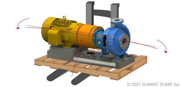
This month, we review the reasoning for multiple pump alignments
and why there may actually be more required than you think!
At the factory… the motor is positioned on the base plate and checked for proper alignment to the pump. As soon as the unit (base/motor/pump) is loaded on the truck the alignment integrity is lost. Later the unit is moved from the truck or warehouse/staging area to the foundation, consequently any semblance of an acceptable alignment tolerance is placed in jeopardy.
Industry best practices (experienced engineers, millwrights, and rotating equipment experts) will tell you that a pump requires a minimum of at least four (4) alignment checks prior to startup/commissioning. There may be an additional 4 or 5 checks to be conducted in the full commissioning process for a possible total of nine (9).
Align the Pump 9 Times
When I tell people that they need to conduct 9 alignment checks in the process of pump commissioning, I receive a wide range of interesting comments…please first let me explain my statement.
One… the first alignment
As mentioned above; prior to shipment the pump is positioned on the base and centered within its bolt tolerance. The motor is then placed on the base and a “rough alignment” is conducted to ensure that a precision alignment is possible and can be successfully conducted later in the field.
There can be exceptions to this example, and it depends on the type and size of driver. The initial factory alignment may only cover the side-to-side adjustments and not the aspects of the vertical or angular offsets, as those will be addressed in the field. No matter how precise the alignment conducted at the factory and how carefully the equipment is transported … the alignment will change in the process.
Second alignment check
When the pump, motor and base are received at the site and initially set on the foundation the second alignment should be conducted to correct for changes in transit. It is critical that the second alignment be conducted prior to grouting or connecting the piping to the pump. Omitting this step is a common and expensive mistake.
Three… the third alignment
You may have thought you had the alignment completed before, but now that the base is grouted you will find that that the alignment has again moved out of specification.
The process of grouting the base will oftentimes warp or otherwise move the base and offset the alignment. During the grout curing process there is a large amount of heat and some expansion force involved that will potentially change the alignment.
Four… the fourth alignment
Now that the base is properly grouted and the driver is aligned to the pump, it is time to connect the piping to the pump. It is always better to “pipe away” from the pump and not from the system to the pump to avoid unwanted moments and forces. Done correctly, connecting the piping to the pump should not alter the alignment in any way. However, from my experience this is a common reason for the alignment to change out of specification and introduce unwanted stresses into the pump.
Alignment steps 5 thru 9
Involve further preventative measures, double-checking and troubleshooting. If you are experiencing issues with alignment procedures and achieving acceptable results in the field, it could be from omitting key steps in the process.Still interested in correctly conducting alignments and commissioning procedures? Please review my articles on this subject for more information regarding the remaining steps by clicking the links below.
-Jim Elsey
Featured, Resources, Summit Pumps
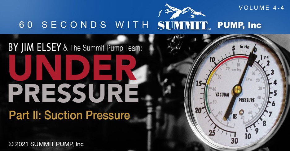
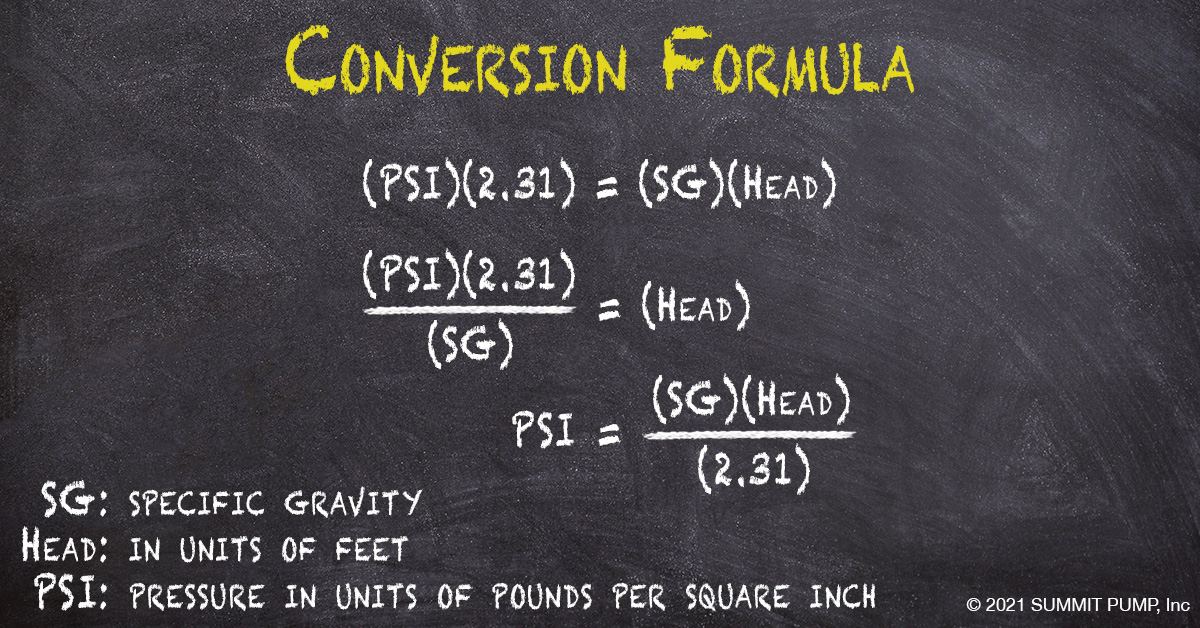
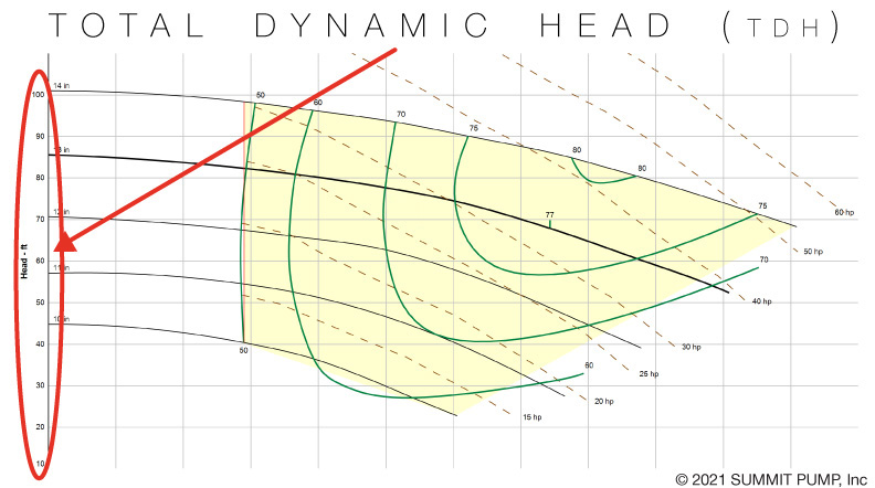
Understanding your suction pressure and knowing how to read a vacuum is critical in identifying performance issues. In the field, instruments measure in units of PSI …whether gauge, absolute or vacuum. When diagnosing issues, PSI must be converted to head in order to calculate Total Dynamic Head (TDH).
Total Dynamic Head
Consider Total Dynamic Head as the amount of energy the pump converts from suction to discharge. This information is critical in identifying where the pump operates on the performance curve.
Suction Pressure
To illustrate reading vacuum or pressure on the suction side of the pump, we will examine both a flooded suction and a suction lift application. Each example will assume the same pump, the same liquid and the same operation speed. The differential pressure of the pump will be the same for each example.
Note: For simplicity, we will not convert pressure readings to head in these examples, but understand the conversion mentioned above must be done in order to calculate TDH. For a more in-depth explanation, see my full article on the topic.
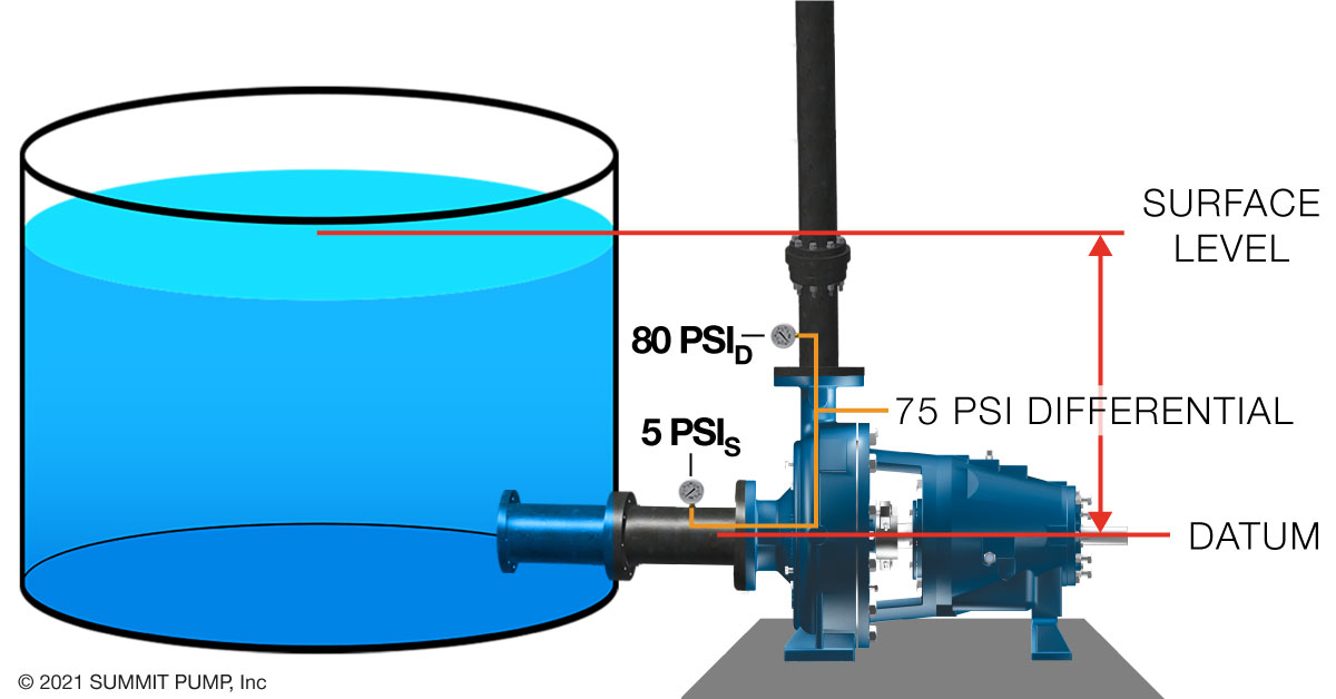
Flooded Suction
In flooded suction, the liquid level is above the pump datum and has energy to provide to the pump. Meaning the pump does not need to convert this energy and will use this “given” energy elsewhere. In this case, a higher discharge pressure.
Suction Lift
In Suction Lift, the pump must generate a low enough pressure at the eye of the impeller to have the fluid pushed into the pump by atmospheric pressure. Energy is used to make this happen and results in less energy available for pressure at the discharge.
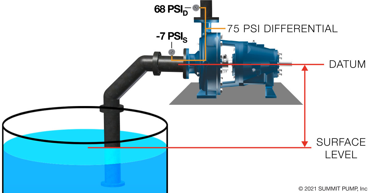
Notice the overall pressure readings are lower but the differential pressure (75 PSI) remains about the same in both flooded and suction lift applications (using the assumptions we made earlier).
Take-a-ways
Pressure gauges neglect velocity energy and read only one type of energy, which is pressure.Understanding your suction pressure and knowing how to read a vacuum is critical in calculating the pump’s TDH (Total Dynamic Head). Knowing the TDH can lead you to resolving several issues including operation cost, safety, pump life, inaccuracy or just nuisance issues.
-Jim Elsey