Featured, Resources, Summit Pumps

Open or Closed Tanks and the Effect on NPSHA Calculations
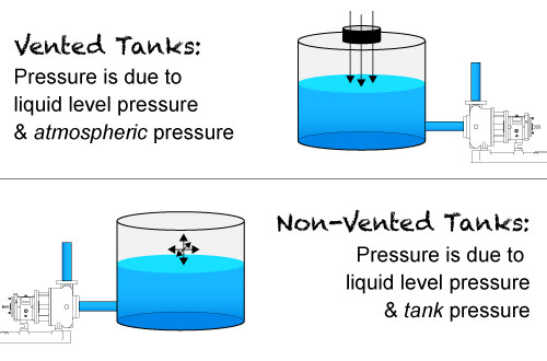
When working through NPSHA calculations for pump applications we need to know if the suction supply tank is open to the atmosphere or not. If it is an open tank the calculation is easy; as we just convert the ambient pressure to head for the first factor in the NPSHA calculation. Don’t forget to convert to absolute values and compensate atmospheric pressure for the local altitude above sea level. If the tank is closed, then we need to do a little more work converting the pressure or vacuum to absolute head for the calculation.
The Issue:
Often the customer will tell us the tank is closed to atmosphere, but it really isn’t; consequently the NPSHA calculations will be incorrect. The resulting NPSHA error will lead to a noncompetitive pump selection.
Sometimes the suction supply tank appears to be closed to atmospheric pressure, but if you look closer at the tank you will see it has breather valves installed. If there is a breather valve installed the tank pressure will always be very close to atmospheric pressure. It is very common, especially in the oil and gas world and also in the chemical and petro-chem arenas to use breather valves on the big bulk tanks. You may actually witness these breather valves on any size tank because the owner needs to protect the investment. Please realize these scenarios may also include rail tank cars, but do not confuse these examples with tank cars that are specifically designed to be pressurized or placed under vacuum for unloading purposes.
The Breather Valves Protect the Supply Tanks from:
- Overpressure (rupture) and or vacuum (implosion) issues
- Fire protection
- Evaporation; loss of product
- Corrosion protection
Another purpose is to prevent excess air and or water (plus other bad stuff like general pollution, O3 and NOx) from destroying the product integrity while it is in the tank. The purpose is to protect the product from outside influence and or to protect the outside environment from the product.
These protection/breather valves are normally required by EPA and or OSHA …they are not just a good idea, they are often a legal requirement in many product applications. Most tank owners apply the same rules to all of their tanks regardless of the product, tank size or location. Note that both the EPA and OSHA will defer to API 2000 for the selection and sizing criteria for the breather valves.
So…I Just Want to do the NPSHA Calculation, What Now?
If the tank has a breather valve, the answer is to simply use the local atmospheric pressure for the NPSHA calculations, because the actual tank pressure is going to be very close.

What if There is no Breather Valve and the Tank is Really Closed Off to Atmosphere?:
When you have a closed tank; I recommend you read my two Pumps and Systems articles on this subject from October and November of 2018, where the basics are covered.
https://www.pumpsandsystems.com/how-calculate-npsha-systems-under-vacuum
https://www.pumpsandsystems.com/calculate-npsha-closed-pressurized-system
If after reading you are still in doubt, call your RSM or engineering for assistance.
Last Comment:
Given a pump system with a supply tank open to atmosphere: note that on the suction line to an operating pump it is not uncommon to have a pressure lower than ambient. You may only expect this situation on a pump that is involved in a suction lift, but even for a flooded suction condition the suction pressure at the pump inlet can be at a vacuum. You can accurately calculate the actual pressure (vacuum) anywhere along the line by using Bernoulli’s Equation. Open and shut case… Easy peasy – lemon squeezy.
References:
OSHA 1910.106 July 1985
API 2000 Venting for Tanks 7th Edition 2014
API 12 (49 CFR 195.264)(b)(1) Specification for tanks
API 650 (CFR 132(b)(3) Specifications for large welded tanks
API Bulletin 2521 (Evaporation Reduction)
API Bulletin 2513 (Evaporation Losses)
EPA 40 CFR 112. Note: This regulation does not actually use the terms “aboveground storage tank.” Instead the term “bulk storage container”.
DOT (various/numerous with respect to rail cars)
-Jim Elsey
Featured, Resources, Summit Pumps
Bringing Awareness to Pump Preservation
Shelf Life:
With the possible exception of Twinkies™*…all things have a finite shelf life.
The purpose of this month’s SSWSP is not to go into the details of pump preservation, but to simply make you aware that it is required. For today we will only discuss new single stage pumps that have not previously been in service.
When you receive a new pump; proper storage procedures must be followed. The enemies are dirt and dust, humidity and temperature, vibrations, ultraviolet light and ozone, and of course the ever present oxidation and corrosion.
 From the moment a casting is poured, or a metal part is ground or machined, an elastomer is formed … without exception… the useful life span clock starts and waits for no one.
When a pump is received from the factory and properly stored indoors, it should be satisfactory for short-term storage. As you approach storage schedules of 3-6 months or longer before startup, you must consider long term storage procedures.
Humidity and Temperature Control:
In the decision process you need to know if the pump will be stored indoors or out and if it is indoors, will the temperature and humidly be controlled. Do not confuse temperature controlled with climate controlled. Climate controlled storage spaces manage both, which together work to regulate moisture levels.
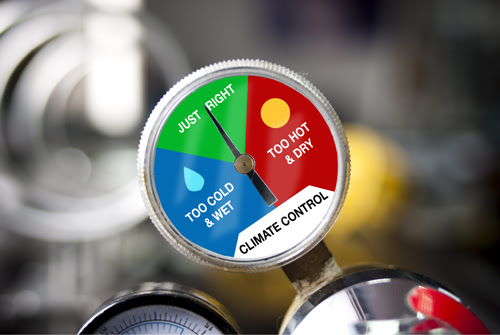 Climate controlled typically means 65 to 85 degrees F with no changes in temperature of more than 10 degrees in one hour. Humidly should be less than 60 percent and often less than 50 percent. Note that pump parts stored below 65 F will not normally be an issue if other parameters are controlled.
There are also Specific Cautions and Procedures for
Rotors, Bearings, Greases, and Seals – Oh My!
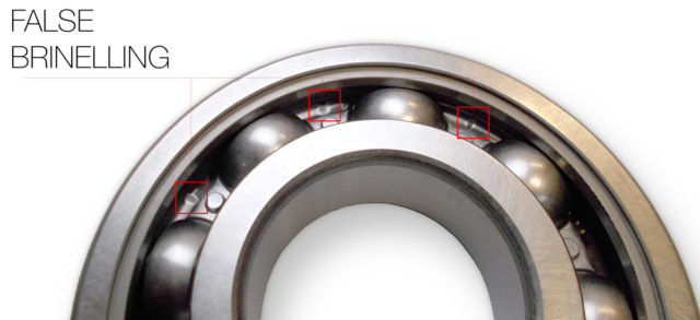
For instance, pump rotating assemblies should be turned by hand every month or two and left in a different position than found to prevent rotor bowing and false brinelling (bearing) issues.
 Note:
Note:
False brinelling can occur simply from small vibrations due to passing traffic and heavy machinery operating nearby.
Sealed for life ball bearings have a 5 year maximum shelve life (due to the grease) even under ideal storage conditions. Mechanical seal assemblies are a detailed combination of metallic and nonmetallic components, which must each follow their own unique preservation regiment.
Ozone:
Exposed (to the atmosphere) rubber products such as spare progressive cavity pump stators and other elastomers are subject to ozone attack. Some elastomers such as EDPM and Viton™ are inherently less prone to ozone issues.
 Procedures:
We have formal engineering procedures to fit most storage situations. We will work with you to make sure the pump and ancillary equipment are stored properly. If you are in a marine, coastal or tropic environment special steps are required even before the pump is shipped.
Postscript:
*The purported shelf life of Twinkies™ …as a millennium, is an urban myth.
-Jim Elsey
Featured, Resources, Summit Pumps

Here are some brief reminders about NPSHA and NPSHR.
NPSH changes with: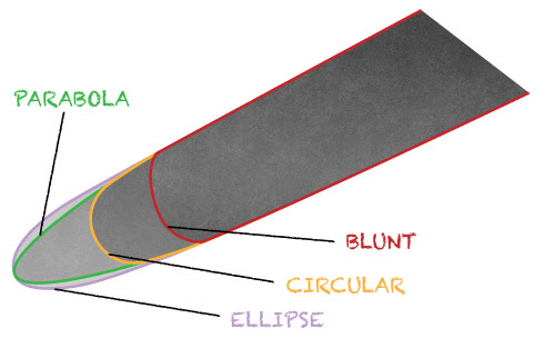
Impeller diameter: For the same flowrate on a given system an impeller of a smaller diameter will have a higher NPSHR.
Clearance of impeller and wear rings: As clearances open up on the pump over time the NPSHR will also increase. This effect is significantly worse for closed impellers than open or semi open styles.
Vane geometry: Specifically the leading edge profile of impeller vanes. The shape of the leading edge will affect NPSHR. Vane geometry in order of best shape to worse shape are 1) parabola 2) ellipse 3) circular 4) blunt.
Speed: Not always 100% true, but for small speed changes NPSHR will vary approximately as the square of the speed ratio for the pump in the midrange operating region and near BEP. For sure, NPSHR increases with speed and vice versa.
Viscosity: Yes an increase in viscosity will increase the NPSHR and decrease the NPSHA. There must be a correction for viscous fluids. In one simple word … friction. See note at bottom for more info.
 Air Entrainment
: Air entrainment in a range of 0.3 to 1.0 percent will actually work to help the NPSH issues, but above 1% the NPSH
R will increase.
Age of system and pump (fouling and corrosion): As systems age and or foul the flow velocity profile and the friction increase. Both factors work to reduce NPSHA and increase NPSHR.
 Suction pipe geometry
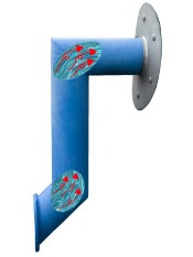
: For every elbow, twist and turn in the suction pipe the fluid velocity profile becomes turbulent (technical for; it gets all messed up) and creates a mismatch (discrepancy) between the fluid velocity and the impeller inlet vane velocity. This mismatch creates recirculation at the impeller eye that directly affects NPSHR.
NPSH Margins: Last; please understand that pumps with adequate NPSH (calculated) margins…where NPSHA exceeds NPSHR can still cavitate, because the margins are not sufficient and the system dynamics are changing.

Quiz: On your own…see if you understand why the following factors affect NPSH.
- Temperature both ambient and fluid
- Vapor Pressure
- Specific Gravity of the fluid
- Elevation above sea level
Bonus Info:
Pumps require a certain amount of Net Positive Suction Head (NPSH) to operate satisfactorily at a given point of head and flow on the curve to prevent cavitation. These points are empirically determined by the manufacturer (sometimes calculated) and are denoted as Net Positive Suction Head Required (NPSHR).
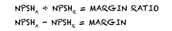
The suction side of the system itself must in return provide a certain amount of NPSH and that is referred to as Net Positive Suction Head Available (NPSHA). There must be more NPSHA than NPSHR for the pump to operate satisfactorily. The difference is referred to as the margin or ratio.
Refer to Hydraulic Institute 9.6.1-2017 for details on margins and ratios.
Viscosity: ANSI/HI Standard 9.6.7- 2015 provides updated instructions for correcting a known water performance into an estimated viscous performance for a given viscosity.
-The Summit Pump Team
Featured, Resources, Summit Pumps
 “Your pump isn’t producing enough flow!”
“I can’t get enough pressure out of your pump!”
“Your pump is making noise!”
We often get these calls from the field. While it is entirely possible, in reality,
it is rarely the pump’s fault.
From my almost fifty years of field experience with pump troubleshooting; I’ve found almost 80 percent of all centrifugal pump issues are on the suction side of the pump. I always start looking there first.
Key Data Needed, Prior to Calling Factory or RSM:
- Pump serial number.
- Fluid properties, or as I like to call it the “fluid personality”. (Temperature / Vapor Pressure / Specific Gravity / Viscosity / Suspended Solids / pH
- What condition was the pump sized for? Flow and head (differential head)
- What clearance is the impeller set at?
- What is the Shutoff pressure?
- Duty Cycle
- NPSHA?
- Submergence?
- Is the pump suction condition in a lift or flooded situation?
- Perhaps supply a sketch or photos of the system showing pipe size, elevations and components. “A picture is worth a thousand words”
- New application or replacement? If it’s a replacement pump, ask why they are replacing it.
The above data should be fairly quick and easy to get from the customer, using a Summit Pump Application Data Sheet. If you cannot solve the problem based on the above data, below are some more in-depth items to investigate further:
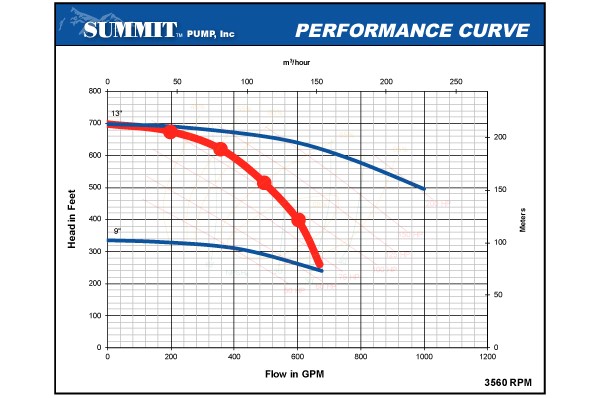
Sketch your pump’s performance against the Summit Pump performance curve.
Further Investigation:
- Confirm pump speed (RPM). This can be done with a tachometer. Be on the lookout for VFD issues, belt or engine driven installations.
- Confirm direction of rotation.
- Proper suction piping per ANSI/HI 9.6.6 guidelines. Proper pipe diameter, length and orientation is critical to successful pump/system operation
- Check the suction source. Is the tank too small, causing turbulence and high velocity? Is there entrained air in the liquid? Is there proper submergence?
- Gauges. Are the proper gauges installed? Are they calibrated?
- Suction lift conditions. Is the lift too high? What is the vapor pressure? Air leaks?
- Head & NPSHa Calculations. Confirm the head & NPSHa calculations. What is the NPSH margin? If the calculations are incorrect, the pump could be incorrectly sized for the application.
- Confirm liquid properties. Is the given information actually the liquid they are pumping? Did the process liquid change? (Specific Gravity, Viscosity, Temperature, Vapor Pressure)
- Pipe Strain. Is the piping properly supported? If not, pipe strain will usually manifest as hot bearings and alignment related issues. Was it laser-aligned?
- Parallel or Series Pumping. If not installed/operated correctly, pumps operating in parallel or series can have problems, and the pump(s) might not perform correctly.
Next Steps:
If you don’t know how to investigate these issues, and/or you are simply not comfortable with the process, we can assist, but please know that we are not system designers.
Featured, Resources, Summit Pumps

Several times a month we receive an inquiry from a concerned customer that the “stainless steel” they received from Summit Pump is magnetic and/or appears to be rusting.
We assure them there is no issue, and explain as follows.
In the case of plain/standard 316-SS, it is usually because the piece has been cold worked and will pick up some magnetic properties. Note if you were to compare the 316-SS to a 400 series stainless you would see an increase in magnitude of the magnetic attraction. It will not attract other ferritic metals, only the magnet, as a result the material itself is not necessarily magnetic, it is ferrous. The magnetic response has no effect on any other property. Austenitic 300 series steels like cold drawn 304 (and to a lesser degree 316) are slightly attracted to a magnet, but this has no effect on its corrosion resistance.
Cold Working: Parts that are highly worked (due to machine operations), such as sleeves and shafts that have been machined, ground and polished, will lend themselves even more to this phenomena.
Corrosion:In 316-SS it is the chrome content that makes it stainless, but it is the nickel content that makes it nonmagnetic.
In the process of cleaning the materials at the foundry and the machine shop, there could be some residual ferrite (iron) from the cleaning process which temporarily alters the surface. The surface may become contaminated on the work site as well. The remedy is to pickle and passivate the surface once again. Stainless surfaces must be kept clean, so the surface can generate the passivation layer and remain as new. It is the chrome oxide film that stainless naturally forms that keeps it from corroding.
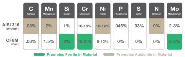
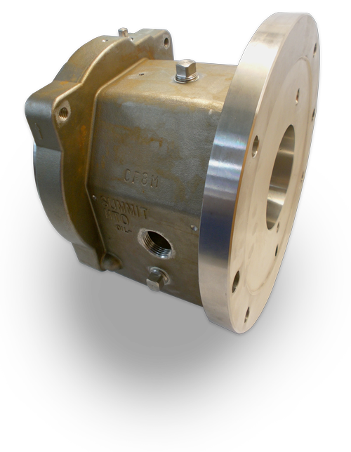
Rolled or Cast: There is a difference in cast stainless steels versus wrought stainless steels that aggravates and differentiates the issue of magnetic attraction. In the case of cast stainless steel, like CF8M, the chemistry and micro structure are purposely different from rolled steel, but the physical and corrosion properties are similar. AISI 316-SS is wrought steel and is notably less or nonmagnetic altogether, as compared to CF8M.
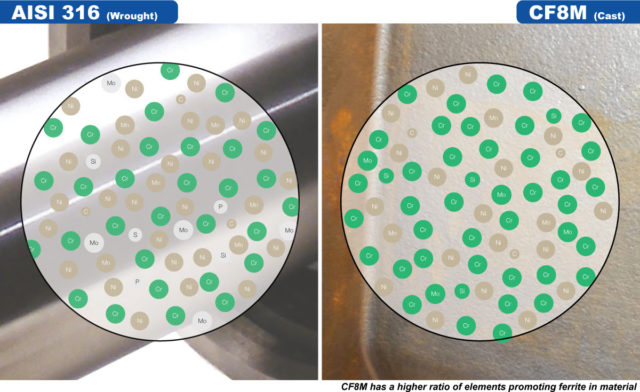
We want some ferrite in the CF8M cast steels to increase the strength and increase its resistance to corrosion cracking. The small amount of ferrite also reduces some forms of corrosion and helps with weldability.
Duplex and Super Duplex Materials: CD4MCu is a duplex stainless steel with magnetic attraction, due to its ferrite content.
If you remain concerned about the material’s magnetic properties, please discuss with engineering or your RSM. It’s possible to perform and document a witnessed PMI test at no charge.
-The Summit Pump Team
Learn More
Jim Elsey’s Pumps and Systems Articles
Featured, Resources, Summit Pumps
Fluid slip is a common term used to describe reverse fluid flow inside a pump or other turbomachinery. Slip is affected by 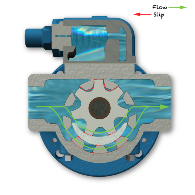 internal clearances of the parts, temperature, pressure and viscosity.
In a positive displacement pump, slip can be easily calculated just by looking at the flow being produced while in operation and subtracted from the nominal flow rate of the pump per one revolution.

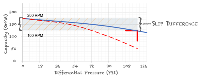
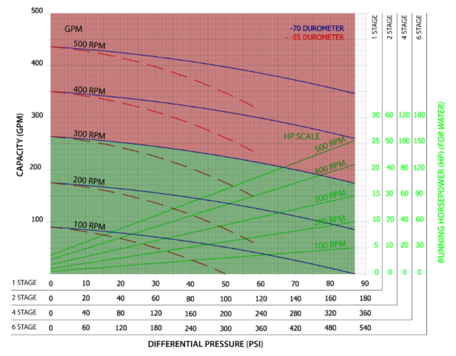
Another way to determine the amount of slip is looking at the pump curve. At 0 psi, the pump is producing its nominal flow at the RPM. Notice as the pressure increases running at the same RPM, the flow will decrease. The difference between the operating pressure and 0 psi is the amount of fluid slip the pump is experiencing. This method is more of an approximation whereas the above measured flow minus the nominal flow per revolution is more accurate.
Why Should we Care About Slip?
Most importantly, too much slip can increase wear and decrease pump life, especially if the fluid is abrasive or has solids. Abrasive fluid passing through the clearances of the internal parts has the same effect of sand blasting. This opens up the clearances even more, amplifying the issue.
Next, too much slip can increase the cost of operation and loss of efficiency. In a positive displacement pump, if you are not getting the desired flow rate the first thing you do is turn up the speed, but doing this also increases the required power needed to meet same flow and pressure.
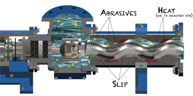
Excessive amounts of slip will introduce heat into the pump. This is critical in both the Progressive Cavity and Internal Gear Pump lines. Elastomers in the Progressive Cavity’s stator, or any rubber, has a set life limit based on how much heat it can absorb. The more heat it absorbs, the shorter its life.
The clearances in the Internal Gear Pump are extremely tight and with extra heat introduced can cause the rotor and idler to expand and potentially lock up against the head or casing. As a side note, if the safety relief valve is being used as a flow throttling mechanism, it can also cause the rotor and idler to expand as well.
How do you Decrease Slip?
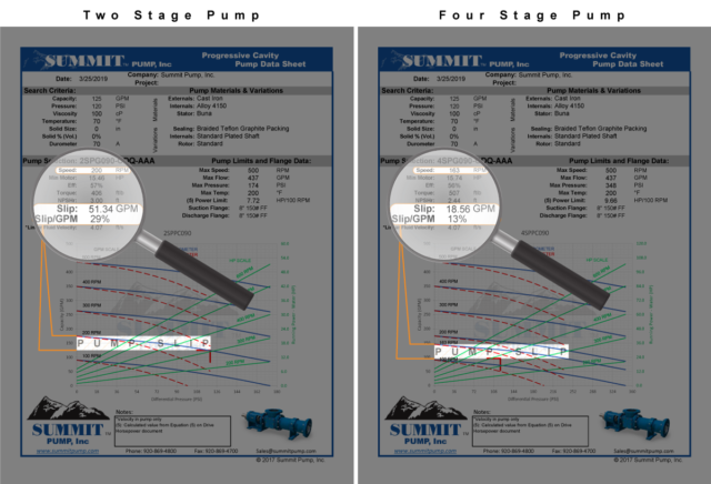
When sizing positive displacement pumps, our guidelines is to keep slip under 15% of the desired flow rate. One option to achieve this is to choose a smaller pump, but keep in mind RPM restrictions. When sizing Progressive Cavity pumps, our guideline is nothing faster than 300 RPM, to minimize the amount of heat generated to maximize stator elastomer life.
 “Summit Pump Man,
I don’t want to change my existing pump size,
what else can I do to minimize slip?”
Reduce the pressure of the system. Reduce the all unnecessary fittings, increase pipe diameter, operate at a lower flow rate, ensure all filters and pipe runs are clean of debris, shorten the distance the fluid has to run.
A convenient feature of the Progressive Cavity pump is the ability to simply change the stage of the pump. For example, increasing a 2-stage rotor and stator to a 4-stage will reduce the amount of pressure per stage the pump experiences. Ultimately, reducing the amount of slip by a factor of the stage change. As with everything, there is always a tradeoff, torque and power required will increase and resulting factors need to be examined, such as motor size, pump frame size and location space available.
-The Summit Pump Team
Learn More
Jim Elsey’s Pumps and Systems Articles