Featured, Resources, Summit Pumps
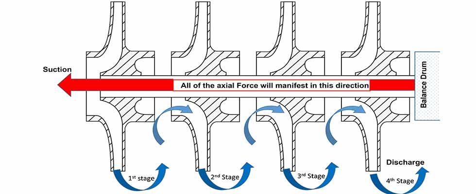
IMAGE 1: Typical multistage pump with impellers all facing in the same direction (Images courtesy of the author)
-Jim Elsey
Balance Drums
In larger and higher horsepower multistage horizontal pumps, all of the impellers face in the same direction (toward suction) and the resultant axial force is almost negated by the use of a balance drum (or simply “drum”). The drum may be of either a straight or stepped design (aka, “two diameter drum”). Some pumps will use balance rings and/or balance discs; these will not be covered. Of interest, know that the axial force can exceed several tons in these pumps.
The drum is keyed and fixed to the shaft after the last stage and, therefore, it rotates at the same speed as and at a fixed position on the shaft. The drum rotates inside of a close clearance stationary throttle bushing. This rotor arrangement and drum geometry permits a small and fixed amount of product leakage back to a chamber that is at or near suction pressure. On a two-diameter drum, the variable axial position of the shaft allows either more or less leakage at any instant to change the chamber pressure on the low pressure side and counteract the axial force. This action occurs instantaneously and automatically as a direct function of the simple design. The amount of total axial movement of the rotor in this evolution is very small—perhaps a few thousandths of an inch.
It is not the intent of this column to describe the balance drum operation in more detail, but a basic description would explain that by using discharge pressure on one side of the drum and suction pressure on the opposite side, the majority of the axial forces will be balanced. Not all balance drum designs will balance the full magnitude of axial thrust as the pump operates over the entire range of its curve, so it may become a case of “caveat emptor,” or in English, “let the buyer beware.”
When you choose a balance drum in the pump design, there is the added cost and complexity of the component itself and its subsequent incorporation into the pump along with the added maintenance. Setting the balance drum clearance(s) in the field is a tedious and complex task that is frequently done incorrectly, all of which leads to expensive damage and downtime. Balance drum designs may also experience significant difficulty with system pressure transients, so always design (size) to have some residual thrust (versus total negation at ideal conditions) with the calculated leakage rates adjusted for a high wear condition. The drum leakage rate does reduce the pump’s efficiency, but in my opinion, it remains an acceptable tradeoff compared with alternative designs in this power range of pumps.
Opposed or Back-to-Back Impellers
A common example of a back-to-back arrangement would be a pump where two single-stage closed impellers are placed back-to-back, one facing each direction so as to balance the axial forces. A partition and/or pressure breakdown bushing between the stages keeps the stage pressures separated. This design balances the thrust almost perfectly and there is little to no reduction in efficiency.
In other large, multistage pump designs, the axial force is managed by using an opposed impellers method, just on a different scale from the back-to-back illustration. For example, in an 8-stage pump, four impellers face one direction and the other four face the opposite way. In this manner, most of the axial force can be reduced. Note that the number of stages facing in one direction is not always an even number when compared to the number facing the opposite direction. On pumps of this style, and especially with four or more stages, you must be vigilant to ensure the rotor is correctly positioned (axially) or there will be issues (damage) with the thrust bearings regardless of type.
The potential remains for high pressure differentials (pressure breakdown) between stages in these pumps and as the wear and subsequent leakage increases with time the thrust will also increase. Years ago, A.J. Stepanoff conducted lab tests on a two-stage (back-to-back) pump. He measured an increase in axial thrust from an initial 200 pounds with the interstage bushing clearance at 0.014 inches to over 1,050 pounds when the clearance increased to 0.060 inches. On many multistage pump models, the downside of the opposing impeller concept is if your system requires an odd number of stages to meet a specific hydraulic condition point. Opposing impeller pumps require a “crossover piece” somewhere in the pump to redirect the flow direction. The crossover casting increases the cost and complexity of the pump.
One last comment on multistage opposing pumps. For this design, there are X number of impellers facing different ways, consequently there are both right-handed and left-handed impellers, and often the first stage is totally different from all the rest (different inlet eye to address net positive suction head [NPSH] issues). To most people and untrained mechanics, all of the impellers will look the same. What could possibly go wrong?
Whack a Mole
The issue of addressing and designing for the pressure breakdown between stages becomes, in my opinion, a game of “whack a mole.” The hypothetical question is: Do you design to contain the pressure per stage, or for some portion of the pump, or for all the stages? For example, on a two-stage pump set up with back-to-back impellers, there is a bushing requirement to contain/control the pressure between the two stages and again at the high side stuffing box. To carry that idea forward, on an 8-stage pump, do you design to break down the pressure after each stage, after four or after all eight?
Dual Suction Impeller
A common example and a slight variation to opposed impeller designs is used on single-stage horizontal split case pumps where one impeller has two symmetrical inlet “eyes” in opposition at 180 degrees to each other. These dual suction impellers are also referred to as double entry impellers. In principle, the net effect is a fully balanced axial force. In fact, the dual suction design is the most successful (but not necessarily the most cost effective) of all the methods. The thrust bearing for these pumps is only required for upset conditions such as startup and shutdown and other off-design operations.
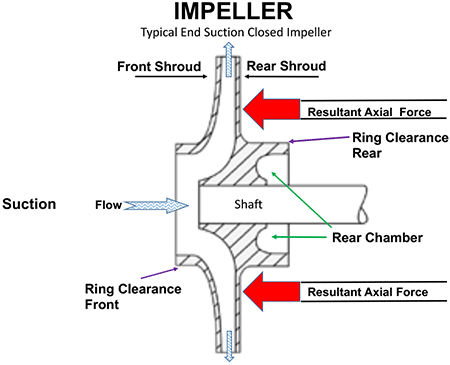
IMAGE 2: Single-stage end suction closed impeller. The resultant axial force will be in a direction toward suction.
As is the case with all pumps, the opposing forces are never fully balanced due to minor differences in the casings and impellers. Understand that these parts are typically cast and carry the potential for imperfections and/or asymmetry inherent to castings. The dual suction design is also limited in the number of stages that can be practically applied, usually three at maximum. At more than three stages, the pump simply becomes too long.
Dual suction impellers may also be applied on the first stage of high end vertical pumps and are frequently used for condensate applications because the net positive suction head available (NPSHa) for these systems is so low and the dual eye impeller requirements for net positive suction head required (NPSHr) will typically be 50 percent of a standard impeller.
Closed Impellers & Use of Back Rings
Closed impellers have both front and back shrouds, and so the surrounding pressure works from both sides of the impeller. There will be a resultant mismatch in the axial force due to the asymmetry of the impeller eye area. The result is less force acting on the eye area and results in a higher force acting on the rear shroud pushing the impeller toward suction.
To counter the thrust mismatch, many single-stage end suction pumps with closed impellers will incorporate a back ring on the rear shroud to reduce the axial thrust. (Some technical references refer to this back ring as an annular seal.) Adding the back ring to the impeller and drilling balance passages (holes) in the impeller shroud creates an area of lower pressure in the chamber behind the impeller. The lower pressure yields a lower axial force. An alternate and, in my opinion, a better design choice is to create an internal passage in the casing back to suction in lieu of drilling balance passages (holes) in the impeller shroud.
The back ring (annular seal) has a similar geometry and appearance of a front wear ring, however, the main purpose is different. The rear ring is there to simply reduce (pressure breakdown) the product leakage into the chamber. Again, by creating the low pressure chamber on the back side of the impeller, the force is reduced.
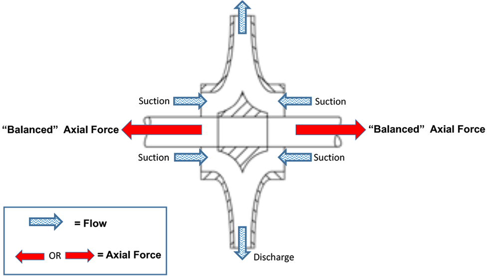
IMAGE 3: Dual suction Impeller. Axial force is balanced.
This back ring feature is common on pumps in heavy industrial and other critical services including many American Petroleum Institute (API) 610 applications. One advantage of the design is that thrust mitigation is not a direct function of the rotor’s axial position. A caveat with this design is that as the back ring clearance wears the effect is diminished. As a result, the magnitude of axial thrust will vary with the ring wear. Some designs will handle this issue better than others due to a better understanding of all of the principles involved, consequently a more accurate calculation of the total area for the balance passages as compared to the annular clearance. Proper sizing and placement of the annular ring as a ratio and proportion of the balance bleed passages is both paramount and critical.
Note that some closed impeller designs will use pump out vanes on the rear shroud, a feature that will be covered in more detail in another section. Some closed impellers will also incorporate pump out vanes on the front shroud of the impeller for the sole purpose of keeping debris away and do not exist for axial thrust mitigation. Other closed impeller designs use pump out vanes on the rear shroud more to rid the area of debris than to reduce thrust.
Not often used in industrial pumps, but some commercial pump casings will incorporate stationary (static) vanes or fins as an integral part of the casing at the front of the impeller to reduce axial thrust.
Featured, Resources, Summit Pumps

In last month’s column (read it here), I began offering pump startup commissioning advice and procedures. As noted, I believe what most folks are actually looking for is the abridged Cliffs Notes version. Nevertheless, there are a few basic steps and overlooked details that, no matter the pump type or application, need to be covered. I started to explain those steps and details in Part 1 of this column. Here is Part 2.
Other Considerations
In no particular order, here is a list of other checks and action steps that are frequently overlooked when starting the pump.
Safety always has to be first and the prime directive. Please realize you could be working with pressurized systems that can be very hot, contain acid and start automatically. You are also standing next to rotating equipment that will unforgivably reach out, grab you and pull you in.
Wherever you are starting the equipment there is almost a 99 percent chance that the owner has some procedures that must be followed.
The most frequent oversight I witness is that the operating manual is cast aside and a long list of incorrect assumptions is formed that includes things that the factory must have done—but they did not. I have written many columns on this subject alone, but you must understand that no industrial pump is “plug and play.”
A simple check is to rotate the pump by hand. The pump should turn freely with no binding/rubbing. Large pumps may require added torque due to inertia that you can overcome with a strap wrench (be careful how and where the wrench is applied to preclude shaft damage).
Rotating by hand should be done after the lubrication is addressed, but before the seal is set. Also, it is much easier before the coupling is assembled.
It is implicit that the unit system must be locked out and tagged out.
Never rotate the pump under power without completing a rotational direction check on the uncoupled driver first. I also recommend a witness and documentation. Incorrect rotation is probably the second most frequent mistake I witness.
Unfortunately, new systems typically have abundant dirt and debris in the lines from construction. It is prudent to install a temporary commissioning strainer on the suction line. The strainer must have a cross-sectional area to allow proper flow and not create NPSH margin issues. The strainer must have some means of measuring the differential pressure across itself, otherwise you won’t know when it is clogged.
Pump systems with long and empty discharge lines will present issues for initial startup; as the line is filling with liquid, there is little to no resistance for the pump and so it will “run out” (to the right) on the curve. You can introduce temporary faux resistance by closing partially on the discharge valve. There is also the increased risk of water hammer and associated damage when the system does fill.
Before the pump is started you should know what flow and pressure to expect on the instrumentation and, oh yes, you need instrumentation. Also, know ahead of time what will be the expected amp reading, frequency (if using a variable frequency drive [VFD]) and perhaps the watt or power readings. I like to bring my own strobe-tachometer, vibration probe and infrared digital thermometer in the event the facility does not have this type of equipment. (Note: You will typically need permission and many facilities will not allow the use of personal equipment.)
Prior to starting the pump ask, is the mechanical seal support system online? This is especially important on API seal pipe plans 21/23/32/41/52/53/54/and 62.
For pumps that use packing in the stuffing box, check to ensure if there should be a flush line and, if so, is it connected to a clean water source? Also check for adequate pressure (flow) to the stuffing box. It is good practice to turn the flush water on prior to opening the suction and discharge valves on the pump. Check with the pump and/or packing supplier for the proper packing leakage rates that will vary with the liquid temperature and its other physical properties, shaft speed and size.
If you can’t find a reliable answer for your application, go with 10 drops per minute per inch of shaft diameter. I typically go with a more liberal 30 to 55 drops per minute regardless of diameter on the initial break-in period.
Make the gland adjustments in small increments, meaning one “flat” per adjustment on each gland nut, and space the adjustments out over 15 to 30 minute increments. The key to proper packing adjustment is patience. Consult with the “Fluid Sealing Association Technical Manual 4th Edition Compression Packing” for more.
You should use all of your senses when starting pumps or any equipment. Look for sparks, smoke and things rubbing that should not be—such as an improperly set bearing isolator or flinger. Listen for the popping of vapor bubbles in the impeller or a squealing mechanical seal that is starving for lubrication. Smell that? Packing is not supposed to smoke. Can you feel the deck and/or the pipe vibrate because the pump is coming off the base due to imbalance or cavitation? Know that you are not at Disney World on an E Coupon—this is the real world with expensive equipment that can crash, burn and hurt you and/or others.
Always minimize the time the pump will be operating at or near minimum flow areas (left side of the curve). Just as important is to not allow the pump to operate at the far right of the curve.
Avoid thermal shock issues if you are pumping something that is hot (above 200 F to 300 F, 93 C to 149 C)—warm-up procedures should be followed prior to startup. Large pumps will likely have minimum and maximum allowable rates of heat up and cool down. Many multistage pumps will require a warm-up procedure that also requires slow rotation on turning gear (aka, jacking gear) for some specified length of time or preordained temperature differential. Remove the pump from turning gear prior to startup. The valve lineup procedure will also include balance drum, warm-up and bypass lines.
Bearing temperatures (or the oil temperature) should be closely monitored on startup. Do not use your hand to feel for the temperature as it is not a precise method and, more importantly, most people will feel a bearing housing at 120 F (49 C) and think that it is really hot. It is not uncommon for bearing or oil temperature to approach 175 F or 180 F (80 C or 82 C). The important parameter to watch is the rate of change in temperature. Fast climbing temperatures are a red flag, and I suggest shutting the unit down and investigating the root cause. Where the temperature is measured is also important; a thermocouple inserted in the bearing is more indicative and timely than bearing oil sump or return path temperatures.
Frequent motor starts often occur during commissioning processes. Be aware of the allowable number of motor starts per unit of time for your motor—refer to National Electrical Manufacturers Association (NEMA) and/or the manufacturer for specifics. Typically the larger the motor and the fewer number of poles will result in a reduced number of starts allowed.
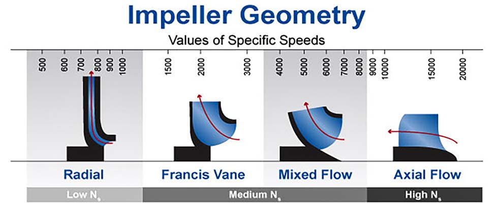
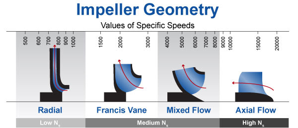
IMAGE 1: Values of specific speeds for different impeller types (Image courtesy of the author)
Discharge Valve Position
I am frequently asked: Should the discharge valve be open or closed when
the pump is started? My answer is it depends, but regardless, the suction valve better be open. First things first—let me state that if you are a visitor to a client facility, you should never supersede their operating procedures.
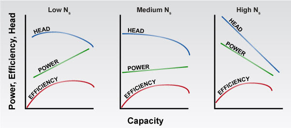
Next, let’s look at the impeller. There are many things to consider, but the primary question we want to answer today is: What is the geometry of the impeller? From that shape we will determine the range of specific speed (Ns). OK, I may have lost you now because I used the nerdy “specific speed” term, but let me explain. For today’s purpose, let’s focus on the directional path of the liquid and specifically how it enters and exits the impeller. Ns is a predictive indicator for the shape of the curves for head, power and efficiency.
Low Ns
If the liquid enters the impeller on a path parallel with the shaft centerline and exits the impeller at an angle 90 degrees to the shaft centerline (at a right angle) then the impeller is in the low Ns range.
Medium Ns
If the liquid enters the impeller on a path parallel with the shaft centerline and
exits somewhere close to a 45-degree
angle, then the impeller is in a medium Ns range. These are mixed flow or Francis vane-type impellers.
High Ns
If the liquid enters the impeller on a path parallel with the shaft centerline and exits in a path parallel to the shaft centerline, this is a high Ns impeller. This axial flow type of impeller would look similar to a boat or airplane propeller.
Plan B
Don’t know the NS of the impeller? Ask the equipment manufacturer.
For low NS pumps, the brake horsepower (BHP) required increases as you open the discharge valve and increase the flow rate; this is a direct relationship just as you would intuitively expect. For medium Ns pumps, the BHP curve and its maximum point moves back to the left some nominal amount. In the past, you may have not noticed this change. Axial flow pumps have a high Ns and the BHP is near its maximum point at the lower flow rates and actually reduces as the flow rate increases. Perhaps the opposite of what you would expect? Notice how the slope of the power graph also changes when the impeller design goes from low to high Ns.
Answering the Original Question
I recommend that the discharge valve be closed on the startup of low Ns pumps and to be open on high Ns pumps. Note: This is a “thumb rule,” and there are numerous caveats that can and will modify the answer. As follows:
1. If the low Ns pump is of any consequential size (flow, head and BHP), you may need to have the discharge valve slightly open to reduce the differential pressure (DP) across the valve. A high DP will prevent opening the valve and this step will minimize the effort to open the valve. Some systems will have a specific bypass line for this purpose. For pumps that have shafts with high shaft stiffness factors (L3/D4 is high), then you will want to keep the time operating on the left of curve as short as possible to ensure a longer seal and bearing life. Note that shaft stiffness factor values are counterintuitive and similar to golf scores. A high number is bad and a low number is good. Finally, note the curve shape; for example, curves that droop near shutoff can place the pump into a situation where it will hunt (oscillate). Consequently, you need to place the pump further out on the operating curve rather quickly.
2. Systems that have downstream pressure (from another source) with no check valves (or check valves that are leaking by) can force the pump to spin backwards when the discharge valve is open. Starting the pump while it is rotating backwards is an excellent method for breaking the shaft. Starting pumps that are in series or in parallel may often require procedures that are too detailed for this forum/column. See local procedures and/or contact the author.
3. If you are starting a pump that will operate in parallel with another pump(s), you need to consider check valve lift points and controlling instrumentation (proportional integral derivative [PID]). Also, when the first pump is started it can run out (far right) on its curve until the second (subsequent) pumps are started. This is too cumbersome to explain in this column.
4. Normally, high Ns pumps are started with the discharge valve open to reduce the electrical load and resultant stresses on the driver. In many cases the driver may not be adequately sized (on purpose) to handle the low flow power requirements and will trip offline.
Shutting Down
Normal procedures for shutting down pumps other than some high Ns types is to close the discharge valve first and then immediately secure the driver. This will mitigate unnecessary stress on the driver and, more importantly, it will reduce or entirely eliminate potential for water hammer issues.
For systems with variable speed drives there will probably be added steps and procedures. Care must be exercised as the driver frequency is turned down if the pump is being operating in parallel, and also due to minimum speed, check valve and system back pressure issues.
Final Pointers
Four last comments and tips to share:
Before you start the pump, know where and how to shut the unit down in case of an emergency.
During the startup evolution, never stand next to or in line with the motor fan or the coupling.
Have the phone number handy for your personal “phone-a-friend pump expert” for when things go wrong.
Always start with the end in mind.
-Jim Elsey
Featured, Resources, Summit Pumps
I am frequently asked for pump startup commissioning advice and procedures—and from experience I begrudgingly predict that what most folks are actually looking for is the abridged CliffsNotes version. I typically start asking specific questions about the pump and the application, but the conversation quickly falters and fades to sports or a binge-worthy series on Netflix.
The Basics
I have personally commissioned hundreds of pumps over my career, from small to really big and with drivers of all types ranging from steam turbines to engines and motors. Not all of these startup events went well, but from the failures came experience and from those experiences came wisdom.
There are a few basic steps no matter the pump type or application that I will cover, and then I will also address the often overlooked details (common mistakes) that can deliver both people and equipment into pump purgatory. For the purposes of this column, I am speaking only for centrifugal pumps and, unless otherwise noted, the pumps are not self-priming. Many of these tips and comments are for initial startups (commissioning evolutions), but will also deftly apply to the pump you start up every Monday morning.
When I am scheduled to supervise a pump startup, I immediately remind myself of one of my old and trusty mnemonic devices. This one is borrowed from the medical profession and in Latin is “primum non nocere” or in English, “first, do no harm.”
Over my career, I have often been summoned to the crime scene as the post-disaster forensic pump pathologist. I have witnessed some expensive startup mistakes that could have easily been avoided if only the operator had simply read and observed a few key points in the instruction book.
Let’s start with a few basic steps that are true regardless of the pump type, model and application.
- You have read and understand the instruction manual and the local facility operating procedure manual.
- Every centrifugal pump must be primed, vented and full of liquid before it is started. The pump you are about to start must be properly vented and primed.
- The suction valve must be fully open.
- The discharge valve may be closed, partially open or fully open; it depends on several factors that are covered later in part two.
- The bearings for both the pump and driver must have proper lubrication—oil at the proper level and/or validation check for the presence of grease. For oil mist applications, you must verify that the generator is in operation.
- Pump packing and/or mechanical seal must be adjusted and/or set properly.
- The driver must be accurately aligned to the pump.
- A full system lineup procedure (valve positions) shall be completed.
- Do you have permission to start the pump (lock out/tag out procedures addressed)?
- Start the pump and subsequently fully open the discharge valve.
- Observe the discharge pressure gauge rise to the proper pressure and the flow meter display the correct flow rate.
- Pat yourself on the back.
Sounds pretty simple so far, but please let me offer some advice. In the words of author Stephen Covey (“Seven Habits of Highly Effective People”), you must “start with the end in mind.” Before starting the pump, did you first envision a smooth operating pump that was producing the proper flow and head while operating at the best efficiency point (BEP) with no problems? If you did, then you missed a few steps in the previous startup procedure.
All too often we will find ourselves at the pump, not properly prepared for the initial startup and accompanied by an impatient operations supervisor pushing to “just start it up.” The issue here is that in reality there is a long list of items that should have been accomplished and/or checked before this high drama startup moment arrives. Pumps are expensive, and you can easily waste all of the cost and more in the one second it takes to push the start button.
Another troublesome issue I frequently observe is that the person with the least amount of operating experience is selected as the supervisor for the startup. The person is selected for several reasons, which are unofficial but nevertheless realistic, including: the startup is on third shift or a weekend or a holiday; the building is not heated; the building is not cooled; there is no building and the weather is miserable; the site is remote; and finally, the fatal assumption that a formal education means you surely had a class on pump startup somewhere in the past.
I will limit the discussion to “things” that are required and or recommended prior to startup. The more complicated the pump and the system, the more steps and checks required. I will not cover more sophisticated installations and procedures, because these operators typically have extensive training and experience.
Regarding proper pump selection, there are also countless numbers of decisions and action steps that should have taken place long before this critical moment we call startup (alternate title: “Things You Should Have Done Prior to or During Installation”).
Examples of these basics that should have been done earlier are foundation design, grouting, elimination of pipe strain, ensuring sufficient net positive suction head (NPSH) margin, pipe size and system geometry, materials choices, system hydro test, system instrumentation, submergence calculations and auxiliary systems.
ANSI Pumps
American National Standards Institute (ANSI) pumps are some of the most ubiquitous pump types in the world. Consequently, I will address a few things that are important for this group.
ANSI pumps include adjustable impeller clearance settings. There are basically two styles that are the opposite of each other, but regardless of the style they must be adjusted to the proper clearance prior to startup. The mechanical seal will also need to be adjusted and set. Note: It is imperative to set the seal after the impeller clearance is set or the setting/adjustment will change.
The direction of rotation on ANSI pumps is extremely important because if the pump is rotated in the wrong direction, the impeller will immediately “expand” (unscrews from the shaft) into the casing and cause expensive damage to the casing, impeller, shaft, bearings and mechanical seal. For this reason, these pumps are typically shipped without the coupling installed. It is essential to perform the driver rotation check prior to the coupling installation. Skipping this step is unfortunately a common problem.
Priming the Pump
Often misunderstood, or simply overlooked, the pump must be primed prior to startup. Even a self-priming pump must be primed the first time. The brief definition of primed means that all the air and noncondensable gases are removed from the pump and suction line and that only liquid is present in the system. If the pump is in a flooded system, the process of priming is easy. A flooded system simply means that the source of liquid is at an elevation above the pump impeller centerline—gravity is your friend in the priming process. To remove the air and noncondensable gases, you still must vent them outside of the system. Most systems will include a vent line with a valve or a removable plug to facilitate this. If there is no means of venting, you will need to be creative, and those methods are perhaps the subject of a future column.
Venting Tips
You cannot properly vent a running pump. The heavier liquid will be expelled while the lighter air/gas and will stay in the middle of the pump, often trapped in the eye of the impeller and/or the stuffing box/seal chamber. Think centrifuge principles of operation and realize water is almost 800 times heavier than air. Improper venting explains that squealing noise you will hear on startup that goes away after a minute and immediately before the mechanical seal starts to leak because it ran dry. Most seal chambers/stuffing boxes should be separately vented prior to startup. Pumps with throat bushings (restrictive) bushings in the stuffing box will present specific challenges to vent. Some designs, specific seal flush systems and some accessories will allow this evolution to occur automatically. Don’t assume your system has the special design.
Vertical pumps present their own special requirements for venting. Because the stuffing box is at the high point, you need to take extra precautions in these cases.
A pump that has a centerline discharge nozzle will typically lend itself to automatic venting, but not necessarily the stuffing box or seal chamber. Pumps that are horizontal split case or have a tangential discharge will require that the casing be vented by some other means. No matter the pump type, the air still needs somewhere to go, so be sure it has a place to go. Magic is not an acceptable response.
Pump Is Not Flooded
When the liquid source is below the centerline of the impeller (lift situation) you will need to vent and prime the pump in some other manner. The three main methods are:
- The use of a foot valve (type of check valve) at the suction end of the pipe. You can fill the suction line with liquid and the foot valve will hold it in the line until the pump is started.
- The use of an external means of drawing a vacuum on the suction line. This can be accomplished with a vacuum pump and ejector or an auxiliary pump—typically a positive displacement pump.
- The use of a priming tank or chamber.
Additional Tips
Foot valves are notorious for failing or jamming at the worst time in either the full-open or full-closed position. You may not realize that it is not working when it fails in a partial position.
Any air in the suction line still needs somewhere to go (otherwise it is trapped), and the pump will not be able to compress it. You will require some type of vent line or automatic air relief valve. If there is a downstream check valve, the pump will not be able to create sufficient pressure to lift and open the check valve.
Self-priming pumps or pumps that are primed from another source will need to have lubrication to the mechanical seal during the startup and priming process. Many self-primers handle this issue with a design that uses an oil-filled seal chamber. Of course, the pump is not necessarily shipped with oil in that chamber, and you need to add it prior to startup. Other pumps will require an external source of lubrication and or independent seal flush system.
Self-primer pumps in operating mode will not leak liquid out of the suction line or the seal chamber because those areas are typically under some vacuum, but do realize that air will leak in.
Keep a record the data: bearing temperatures, flow, pressure (head), amps, voltage, frequency, vibrations and ambient conditions.
Part 2 of this column will appear in the next issue of Pumps & Systems. Read it here.
-Jim Elsey
Featured, Resources, Summit Pumps
I’ve been around for a while and have observed the parade of fashions and trends coming and going through the years. From my college days in the ’60s—miniskirts, peace signs, corduroy pants, tie-dye and paisley shirts were “groovy” and “far out.”
Now 50-plus years later, many of these faded ideas have made a resurgence, at least in some circles. Perhaps some of these fashions and trends were good ideas and some were not. In retrospect, I have few regrets of my own personal choices from the past, but I do wish I had held on to my car, a muscle car that I street raced.
Thinking back to my car from the ’60s, I typically evaluated my odds of winning or losing the race by estimating the car’s horsepower to weight ratio as compared to my opponent. Going forward in the pump business the last 50 years, end users have also pushed industrial pump manufacturers toward a similar goal—exponential horsepower increases for more head and flow—all contained within smaller and smaller pump sizes or, simply, get more with less.
Suction Energy
I have been involved with industrial rotating equipment in one way or another since those days of wearing bell-bottom jeans, and sometime in the last half century, I was also exposed to the theory of suction energy (SE). SE is a concept that explains how the momentum of the fluid entering the pump suction can potentially be an issue or not. Similar to disco music, it appeared to be a good idea at the time. Thankfully it faded quickly and, like an odd wrench in the bottom of my toolbox, I did not use it anymore, but I could not throw it away either.
I dismissed the practicality of SE in a column many years ago; however, I am seriously rethinking the decision because I am now looking at it in a different way. Many readers may not have heard of this thing called suction energy. SE is, in essence, a measurement of the liquid momentum at the impeller eye. SE, in its simplest definition, is the unit-less mathematical product of the nominal inside diameter of the pump suction nozzle (D), multiplied by the pump speed (N), multiplied by the suction specific speed (Nss). Note: The speed is revolutions per minute (rpm) and the diameter is inches.
Formula 1:
Suction Energy = D x N x Nss
A more refined definition of SE exchanges the first factor of the pump suction nozzle size for impeller inlet (eye) size (De). Note: They are frequently close to the same dimension. Specific gravity (SG) was also added to the formula and, if pumping cold water it is obviously not a factor, but if pumping hot water or a different fluid, the factor should be weighed.
Formula 2:
SE = De x N x Nss x SG
If the impeller eye diameter is unknown and cannot be determined, you may estimate it by using the following factors: For an end suction pump, multiply the suction nozzle size by 0.9, and for a horizontal split case or radial inlet pump, multiply by 0.75.
Defining Levels of SE
The results of these equations produce high numbers, and so it is common to use a form of short-hand scientific notation, but the coefficient remains as a three-place number.
- Low SE is defined as values below the high SE levels.
- High SE is defined as values at or above 160 x 106 for end suction pumps and 120 x 106 for split case and radial inlet pumps.
- Very high SE is defined as values at or above 240 x 106 for end suction pumps and 180 x 106 for the split case and radial inlet pumps.
Pumps Have Boundaries
We are still not allowed to violate the laws of physics, and so this imposing goal of more with less requires improved impeller designs, higher rotating speeds and fluid velocities. Along with the benefits of more horsepower and head (generated per stage) all in a smaller box, there are caveats that require higher net positive suction head (NPSH) margins, diminished operating ranges and often more wear.
Technological advances have helped us design and manufacture better pumps since Lyndon Johnson and Richard Nixon were president, but some consequences will defiantly persist, simply to cruelly remind you of the serendipitous karma that pervades our universe.
And this brings me back to the subject of SE and the suction side portion of the pump system. Most pump manufacturers will ask for a minimum of 10 or more diameters of straight, unobstructed piping prior to the pump suction flange in a seemingly fair exchange for a trouble-free and reliable pump. This means no valves, no elbows, no tees, no strainers, no reducers and surely no flow meters. In the unfair light of the real world, the pump never gets to check off any of the boxes on this wish list of desired requirements.
Additionally, it is highly suggested that the liquid velocity in the pump suction inlet piping should be less than 10 feet per second (3 meters per second—slower is even better). This velocity requirement is also often cast aside.
To oversimplify what can be a complex design requirement at the entrance to the impeller, in a perfect world we are looking for an equalized hydraulic loading with zero pre-swirl, eddies and recirculation in the fluid as it is presented to the impeller around the entire 360-degree profile. When the SE level is low, the pump owner can often disregard many of these aforementioned requirements and still avoid the downside consequences that would normally result with these violations.
What I witness more and more with industrial applications are suction side issues that could have been avoided if the end user had paid more attention to the suction system from the dual aspects of energy (suction energy) and piping geometry.
What I frequently hear is that there is enough net positive suction head available (NPSHa) and the margins are adequate or the specific speed (Ns) and/or the Nss is in an acceptable range—so, what is the problem?
One of the remaining unaddressed issues is uneven hydraulic loading of the impeller with copious amounts of pre-swirl, recirculation and high velocities. One recent application I visited had more than six obstructions introduced in three different planes within the last 10 feet of suction piping. There was adequate NPSH margin, but the pump was in the very high range of SE and, consequently, the pump was not performing properly.
What I am ultimately trying to do is help the owner-operator have a reliable pump and operating system. I don’t know where all the boundary lines are exactly for your specific application.
Additionally, note these guidelines and guardrails are often grey areas—not black and white. There are also no flashing red warning signals for the inexperienced designer.
Another way to say all of this is: If you have adequate NPSH margins and properly selected impellers for the operating range, you still need to evaluate your total system design. The typical design will be a compromise based on best practice hydraulics on one side and the initial cost of the system on the other. What many organizations do not allow is an evaluation of pump/system reliability and the associated cost over some period of time, perhaps five to 10 years or even 20.
Look at the SE level of your system and if it is low, then perhaps you have nothing to worry about and can move on. However, if it is at a high or very high level, then I suggest that you re-examine your system design with a higher degree of due diligence regardless of the NPSH margin and the impeller geometry.
Prediction Clues
When you have pump and system issues and can’t seem to figure it out, look at the SE level and, in conjunction with that data, also consider these additional prediction factors/indicators of pump issues.
- liquid personality: temperature, viscosity and specific gravity
- impeller speed: watch for inlet tip speeds above 75 feet per second (above 100 for sure)
- pipe size suction: typically the size should be one size larger than the pump itself; in some high energy cases, you may want to design even bigger
- fluid velocity suction: looking for less than 10 feet per second at the suction
- pipe geometry (suction side): looking for elbows or components to be far
- from the pump suction nozzle, proposing 10 diameters
- impeller type: dual suction/shaft through the impeller or end suction
- impeller: number of vanes
- impeller vanes: the absence of—or the amount of vane overlap
- impeller: inlet incidence angle and also compare that angle to suction nozzle
- suction specific speed (Nss) and the D2 over D1 ratio
- specific speed (Ns)
- NPSH margin: even with an adequate margin, operating left of the best efficiency point (BEP) can be an issue when the SE is high
- operating point on the curve relative to the BEP
Additional Perspective
If you have a system that seems plagued with unexplained pump issues, take a look at the SE level. Professional engineer Alan Budris, who is a leading expert in the pump world and a champion of this concept, has successfully corrected system issues for clients when he persuaded end users to change to a different pump (or sometimes simply an impeller change) at a lower level of SE. This is not covered here, but there are additional tools that use the SE and NPSH margin ratios.
In a Pumps & Systems article from February 2012, Terry Henshaw, whom I respect deeply, questioned the concept of SE and suggested it was perhaps a flawed concept. Henshaw argued (and I am surely oversimplifying here) that when you algebraically compare the SE formula to NPSH, pump speed and Nss, many aspects (factors) are diminished or even eliminated. I agree with the argument as it was presented. I postulate that maybe there are ranges were SE is more important than in others?
However, my main point for this column is this: When making pump application decisions, the ultimate goal is to win. And just like on the race track from years ago, I want every competitive advantage I can garner.
-Jim Elsey
Case Studies, Featured
A case study in how to transfer liquified gases (propylene, in this application) using the vapor itself.
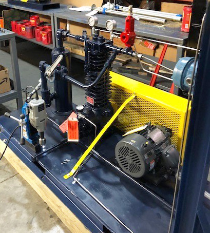
Custom-built, explosion proof Blackmer compressor package exceeded our customers expectations!*
There are challenges when transferring liquids that are vapors at atmospheric pressures. Liquids like ammonia, butadiene, propane, propylene, refrigerants, or vinyl chloride must be contained under pressure to keep them in equilibrium. Pumps, with the limited Net Positive Suction Head available (NPSHA), cavitate and can become vapor locked.
Using Blackmer HD gas compressors to compress the vapor to transfer the product is much more efficient. Transfer faster and recover much more product with the Blackmer HD compressor.
A global chemical manufacturer (and their engineering firm) asked for “Liquid transfer of propylene from a 435 lb. cylinder to a 125 gallon storage tank and transfer from the storage tank to a feed tank”. Conditions: 20F, 57 psi inlet pressure/77 psi discharge pressure; 70F, 140 psi inlet pressure/166 discharge pressure; and 100F, 210 psi inlet pressure/230 discharge pressure thus the compressor was going to see varying conditions although the differential pressures (discharge minus suction) were pretty constant at 20 psid to 26 psid.
Using a Blackmer compressor for liquid transfer and vapor recovery
How it works:
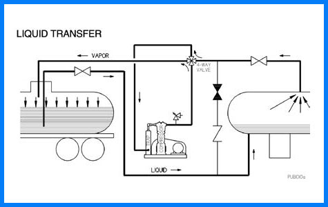 LIQUID TRANSFER
The compressor and 4 way valve is configured to allow the destination vessel vapor to enter the compressor where the gas is slightly compressed and discharged to the top of the source container or vessel where the gas pushes on the top of the liquid forcing the liquid up the liquid line connected to the bottom of destination vessel.
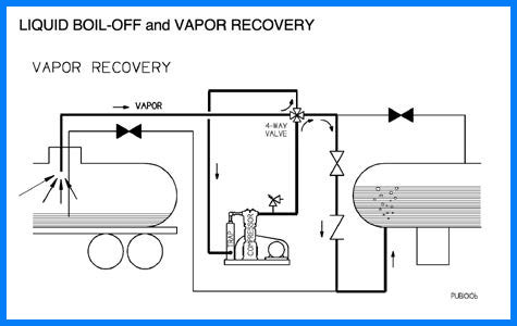 LIQUID BOIL OFF AND VAPOR RECOVERY
When nearly all the product is transferred, you are left with a small amount (heel) at the bottom. You then change the 4 way valve and other valves to allow the vapor line from the source vessel to connect to the compressor inlet and you compress that gas and push it up through the bottom of the destination vessel. As the gas travels up through the liquid, it cools and tends to condense into liquid. This operation continues until the pressure in the source vessel drops to a pre-set point (typically dictated by economics).
The compressor transfer process described is done with many liquified gases and natural gas with the same basic process steps.
As a long-time distributor for Blackmer, we were able to provide a Blackmer gas compressor package for this important application.
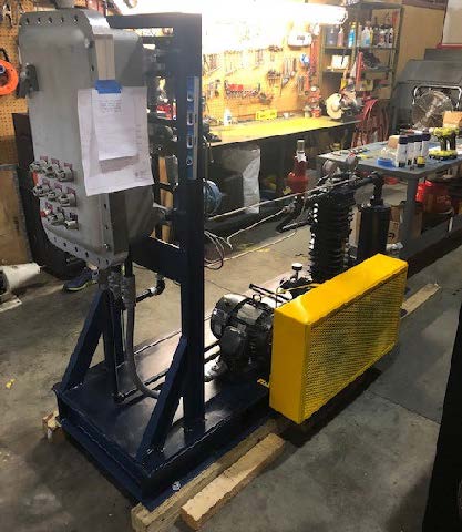
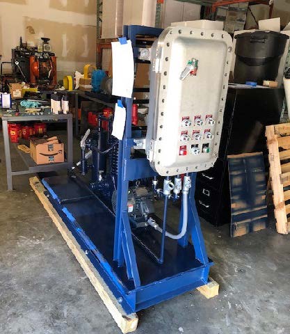
Our design team assembled a complete package in our Louisville facility per the customers requirements from the ground up, including a custom steel base with forklift portability, and a complete controls package for “plug and play” installation.
* Our customer asked for 15 minute liquid transfer and we did it in about 5 minutes!
Backside of Nema 7 control panel showing Nema 7 controls which were prewired and connected to compressor and panel.
Application details:
Liquified gas transfer of propylene from 435-gal cylinder to 125-gal storage tank and transfer from storage tank to feed tank. 4 SCFM @ 77 PSIG, 166 PSIG and 231 PSIG.
Custom compressor package:
- Blackmer heavy-duty compressor model HD082B (Blackmer’s smallest HD size) – non-lubricated, 1-stage, vertical, air cooled, single cylinder, single acting, ductile-iron construction with packing.
- 76”x26” structural steel baseplate with V-belt drive, belt-guard, motor slide base, liquid trap, 4-way valve and strainer.
- 3-HP, 1750 RPM, 182T frame explosion proof motor, belt drive.
- NEMA7 Low oil pressure switch, low suction pressure switch, high discharge pressure switch, high temp switch and SS high liquid level float switch.
- Discharge relief valve ASME.
- Mounted and wired NEMA 7 control panel with start/stop push button, Power “on” light, Production test report and hydrostatic test @ 503 PSIG.
Blackmer heavy-duty compressor model HD082B mounted on structural steel baseplate.
Featured, Resources, Summit Pumps
I am frequently asked; should the discharge valve be open or closed when the pump is started? My answer is….it depends, but regardless the suction valve better be open.
First Things First
Let’s look at the impeller. There are many things to consider, but the primary question we want to answer today is; what is the geometry of the impeller? From that shape we will determine the range of Specific Speed (NS). Ok, I may have lost you now because I used the nerdy “Specific Speed” term, but let me explain. Just for today’s purpose, let’s focus on the directional path of the liquid and specifically how it enters and exits the impeller.
Specific Speed is a predictive indicator for the shape of the curves for head, power and efficiency.
Low Ns
If the liquid enters the impeller on a path parallel with the shaft centerline and exits the impeller at an angle 90 degrees to the shaft centerline (at a right angle) then the impeller is in the low Specific Speed range. This would be a typical radial impeller like the Summit Pump model CC-FM.
Medium Ns
If the liquid enters the impeller on a path parallel with the shaft centerline and exits somewhere close to a 45 degree angle, then the impeller is in a medium Specific Speed range. These are mixed flow or Francis-Vane type impellers.
High Ns
If the liquid enters the impeller on a path parallel with the shaft centerline and exits in a path parallel to the shaft centerline, this is a high Specific Speed impeller. This axial flow type of impeller would look similar to a boat or airplane propeller.
Plan B
Don’t know the Specific Speed (Ns) of the impeller? Ask the manufacturer.
Now for the Really Interesting Part
For low Specific Speed (Ns) pumps the Brake Horse Power (BHP) required increases as you open the discharge valve and increase the flow rate, this is a direct relationship just as you would intuitively expect. For medium Ns pumps the BHP curve and its maximum point moves back to the left some nominal amount … in the past you may have not noticed this change. Axial flow pumps, of high Ns, the BHP is near its maximum point at the lower flow rates and actually reduces as the flow rate increases. Perhaps the opposite of what you would expect? Notice how the slope of the power graph also changes when the impeller design goes from low to high specific speed.
And…Answering the Original Question
I recommend that the discharge valve be closed on the startup of low Ns pumps and to be open on high Ns pumps. Note, this is a “thumb rule” and there are numerous caveats that can and will modify the answer.
- If the low Specific Speed (NS) pump is of any consequential size (Flow, Head and BHP) you may need to have the discharge valve slightly open to reduce the differential pressure across the valve. This step will minimize the effort to open the valve. Some pump systems will have a bypass line for this purpose.
- Systems that have downstream pressure (from another source) with no check valves (or check valves that are leaking by) can force the pump to spin backwards when the discharge valve is open.
- If you are starting a pump that will operate in parallel with another pump(s) you need to consider check valve lift points and controlling instrumentation (PID); this is a subject too cumbersome to explain in the “Sixty Seconds” platform.
- Normally, high Specific Speed (NS) pumps are started with the discharge valve open to reduce the electrical load and resultant stresses on the driver. In many cases the driver may not be adequately sized (on purpose) to handle the low flow power requirements and will trip offline.
-Jim Elsey
I started this discussion about why some impellers have holes in them, or why some impellers have funny mini-vanes on the back side. The short answer, as I stated last month, is to reduce axial thrust, reduce the pressure in the stuffing box (seal chamber) and to preclude the collection of foreign debris in the annulus (chamber) behind the impeller.
Here is where we left off from Part 1 of that column (which you can find here).