

Ever wonder why some impellers, all sparkly fresh and new from the factory, have holes in them, or why some impellers have those funny mini-vanes on the back side? The short answer is to reduce axial thrust, reduce the pressure in the stuffing box (seal chamber) and to preclude the collection of foreign debris in the annulus (chamber) behind the impeller. You may think that internal pump forces are not important, that the thrust bearing in the pump is really just window dressing and pump operating/running clearances have little to do with any of this. Unless your pumps run trouble free for more than five to eight years between maintenance, perhaps there is something here.
Regardless of size or design, whenever you operate a centrifugal pump, there are always dynamic forces to be managed and collectively known as the “total dynamic load.” The total dynamic load is the summation of all the forces that manifest throughout the pump as either radial and/or axial loads. The pump designer will address all of the forces by incorporating features to manage, reduce and/or eliminate the effects. And of course, as with everything in machinery, computer software and real life, there are always compromises to be made. Grandma always said, “You can’t get something for nothing.”
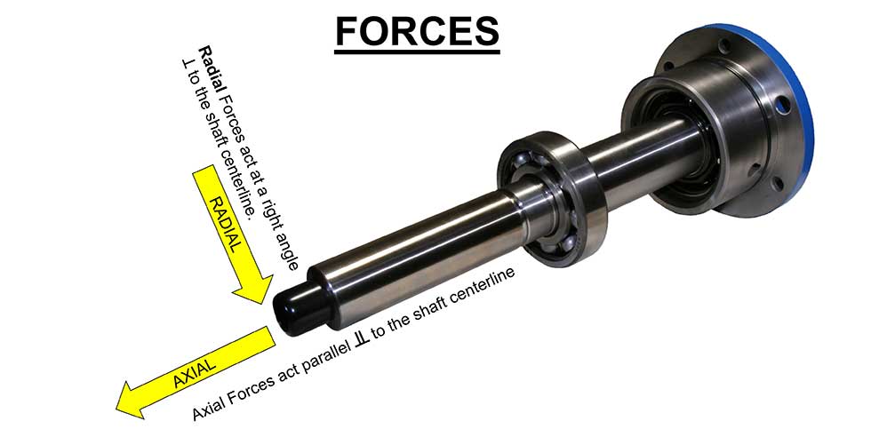 IMAGE 1: Radial or axial, the resultant forces are mostly due to the hydraulic pressure acting on the impeller. F=PA. Force is equal to the pressure (P) working on the effective surface area (A) presented by the impeller shroud(s). (Images courtesy of the author)
Axial Force
There are several dynamic factors that must be addressed in the pump, but the two important ones are the axial and radial forces. This column will address the management of axial forces in the pump. We will look at radial forces in a future column. The actual magnitude of these forces is calculable, but we will skip over those formulas this time and just address the cause and effect.
Axial forces are those that act on the rotor in a direction parallel to the shaft. Axial force, if not properly addressed, will try really hard to push the rotor out one end of the pump. In reality, there are forces acting in all directions on the rotor, but it is the vector summation of the axial components that is our concern for now.
Force (F) as defined for this application, is the total summation of the pressure applied per unit area. Therefore, the higher the pressure and/or the larger the area, the greater the force. The fundamental equation is F = PA; where P = pressure and A = area. This force is also a vector and so it has properties of both magnitude and direction.
The resultant axial forces in the pump exist due to higher pressures acting on one side of a surface and/or acting on a larger surface area when compared to the opposite side. The major thrust contributor in the pump is the pressure working on the large surface areas presented by the impeller shroud(s). But realize that shaft shoulders and impeller hubs also present surface areas and even the small diameter at the end of the shaft (protruding out of the pump at the coupling end) has atmospheric pressure pushing on it.
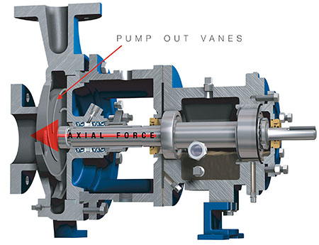
IMAGE 2: Pump out vanes are one method to manage axial force.
In every case involving axial thrust, the magnitude will be proportionally reduced by an increase in the suction pressure when compared to atmospheric, but of course at some point the suction pressure can be too high for the pump casing or related components such as the packing or mechanical seal. After balancing or reducing most of the axial forces in the pump, the residual axial forces will still need to be carried by the thrust bearing. The thrust bearing transmits the axial force to the pump frame housing and eventually to the foundation.
As hypothetical design questions, ask yourself what type and size of thrust bearing would you put in the pump, and then ask how long do you want the bearing to last? Finally, if the thrust force doesn’t have a pump foundation to transfer to, where does it go?
Methods to Manage Axial Forces in the Pump
There are several methods used in modern pump design to both mitigate and address the effects of axial force. Each approach has positive and negative attributes. Not all methods are covered in this column.
The pure mechanical approach simply designs the thrust bearing to absorb all of the thrust.
Next, there is the hydraulic configuration approach that attempts to reduce the thrust as much as possible via the basic pump design. For example, a back-to-back impeller pump where thrust is balanced due to symmetry. Other methods employ design features and balancing devices that address the forces by using balance drums, balance passages (holes), back ringed impellers, pump out vanes or some combination of these methods. Regardless of the approach in the real world, the pump will still require a thrust bearing of some type and size because no pump (or system) is perfectly balanced over the full range of operations.
Vertical Pumps
Vertical pumps, like the turbine style, will typically use a thrust bearing in the motor that is designed to carry all of the axial thrust from the pump. This is a unique design feature compared to all other types of pumps. There are exceptions were the pump thrust bearing is incorporated into the pump support housing.
Most vertical pumps will have all of the impellers arranged in the same direction. There are industrial grade multistage process pumps that will incorporate a crossover component so that half (or some design mandated percentage) of the impellers are facing one way and the remaining face the opposite direction. A few designs will also incorporate a double suction first-stage impeller.
This column is not covering all types of vertical pumps, and I will not address vertical submersible or cantilever pumps.
Within the normal range of operating conditions, a vertical pump will experience a resultant downthrust, which places the pump shaft in tension. The rotor is designed to be in tension and will experience issues when it is not. Consequently, if there is an upset in pump operations where an upthrust condition overcomes the downthrust for any length of time, there can be serious problems including bearing damage and shaft breakage. Most vertical pump rotors and the motor thrust bearing are designed to accommodate momentary thrust upsets that occur during startup and shutdown.
During normal pump operation, the magnitude of the thrust factor varies with the impeller design, the number of stages, the length of the pump, where the pump is operating on its performance curve and the head generated per stage. Some impellers are hydraulically balanced and some are not, and on some pumps it is a simple option for the application engineer to select on the build sheet to choose either. Consequently, the feature of balanced impellers needs to be declared to all the cooks in the kitchen, especially when choosing the driver and the thrust bearing.
It is both important and prudent to discuss all of these details with the manufacturer and/or an expert in the matter prior to changing where and how the pump will operate. Something as simple and unexpected as changing the type of bowl bearing, radial line shaft bearing or a change in the axial clearance setting (lift) could affect the success or failure of the pump application.
Vertical pumps: locating the pump thrust bearing in the motor makes for a more unique (less interchangeable) and expensive motor. On the pro side of the pros and cons list is that the motor is specifically designed for the application.
Vertical pump impellers typically do not use pump out vanes (for thrust reduction) in the majority of designs because of axial clearance uniformity issues when setting the pump rotor lift (short version is variance and stack tolerances), but many designs have the option to incorporate balance holes in the impeller(s) to reduce the thrust.
-Jim Elsey