Why Is Your Pump Operating Off the Curve?

“Wishin’ and Hopin’”—both Dionne Warwick and Dusty Springfield had hit versions of this pop song in the early ’60s. The lyrical message is that you will not get want you want if you just sit around wishing and hoping; instead you need to take action to achieve the desired outcome.

The same advice holds true for pump performance. I witness an alarming number of people who unwittingly wish and hope their pump would perform in the proper manner, but they are wishing and hoping with total disregard of the system curve, pump capabilities, the laws of physics and the fluid properties. Time to take action.

I start my pump training courses with the simple personification that “pumps are stupid.” Put a centrifugal pump in any system, and it does not know where to operate. It is the system, not the pump, that dictates where the pump will operate on its performance curve—if the pump is even capable of operating at that point.

Further, and intended only as a comedic anecdote to help my students learn, I refer to the pump as the “husband” in this marriage with the system curve, aka the “wife.” Perhaps, and with ostensible apologies to the “PC Police,” I suggest that the marriage works best if the husband (pump) listens and obeys the wife (system). If there is a mismatch in the two, then divorce (pump and system failure) is imminent.

The pump will operate where its performance curve intersects the system curve, but we don’t always know where that point is—and just to complicate matters, it can change quickly because of many variables. Two roadblocks that make this determination difficult are:

  1. We frequently have no idea of the system curve geometry
  2. The pump is often forced off its published curve by outside factors

We will address the system curve calculation in a future article. For now, the system curve is the absolute summation of the system’s static head, pressure head, velocity head and friction head. The geometry of the system curve is directly related to the flow rate, pipe size, elevation changes and losses due to friction of all the components in the system. Note the system curve is dynamic and will change with tank elevation and system pressure changes. It will also change with valve position, system age, fouling and corrosion. This month’s article will address No. 2: How pumps can operate off their published curves, and we will look at a few common examples.

Causes for Operating Off Curve

Here are some of the common issues:

  • worn clearances
  • different or incorrect size impeller
  • different or incorrect speed
  • viscosity not corrected or accurate
  • net positive suction head (NPSH) margin insufficient
  • air entrainment and/or dual phase liquids beyond 3 percent
  • inadequate submergence (also see air entrainment)
  • partial or restricted blockage of the suction line
  • operating the pump in the wrong direction

First Things First

To determine where your pump is really operating, you will need to calculate the pump performance curve in the field “as is.”

First, obtain a copy of your pump performance curve as published or purchased. Then, using the pump’s discharge valve position, create a series of several different flow rates (recommend at least six points including shutoff head), determine and record the suction and discharge pressures for each flow condition, convert these pressures to differential head and plot them on your curve. Be careful to correct for gauge elevations, temperatures and specific gravities.

Does your curve match the published curve? If it does within 5 to 10 percent, then there is likely no problem.

Let’s look at a few cases where the curve does not agree with the published curve. Each case tells a critical story to help understand what is happening with your pump and the system.

Worn Clearances

As a pump wears, the hydraulic performance deteriorates. Most people understand the pump efficiency will drop due to wear, causing the power to increase, but not all users realize that the head and flow will also deteriorate.

Note the revised pump curve still intersects the system curve, but the meeting point is at a lower flow rate and a lower head. See my Pumps & Systems articles from January 2016 and July 2017 for more details on this subject (Image 1).

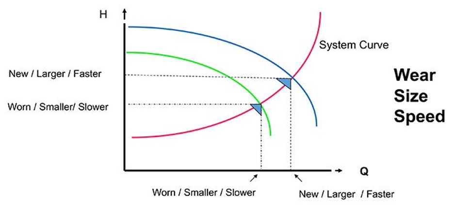
Image 1. Effect on pump performance with wear, speed, impeller size (Images courtesy of author)

It is important to understand if you are also plotting power on the curve: if the wear is simply the impeller or casing wear rings, the power will increase noticeably. But if the wear is in other areas such as internal passages, cutwater or the impeller vanes, the power will only increase a small amount.

A special note for ANSI pump designs that use the critical clearances between the impeller and the casing or stuffing box: the effect on power will be as the aforementioned pump with wear rings—that is, the power will increase noticeably.

Different Impeller Size or Speed

Often, one of the reasons for poor pump performance is that the wrong size impeller is in the pump. This could be caused by several different reasons, mostly human error. Another common reason is that the speed is different than perceived. This is common with systems that are controlled with variable frequency drives (VFDs) as part of the system control process. I mention both of these issues (speed and diameter) here because the performance manifests almost exactly the same as worn clearances.

See Image 1 to see the performance of smaller impellers or lower speeds.

Viscosity—the Kryptonite of Centrifugal Pumps

Viscosity has a direct and negative effect on centrifugal pump performance. The pump efficiency is affected the most, but head and flow are not far behind. Of course, all of these negative factors will contribute to increase the power required to pump the fluid at the same flow rate and head as if based on water performance.

Note that viscosity is directly proportional to temperature, so be cognizant of the fluid temperature. Also, smaller pumps are more affected by viscosity due to the smaller passage size.

See Image 2 for how viscosity will affect the pump performance, and also refer to my article on this subject from the November 2017 issue.

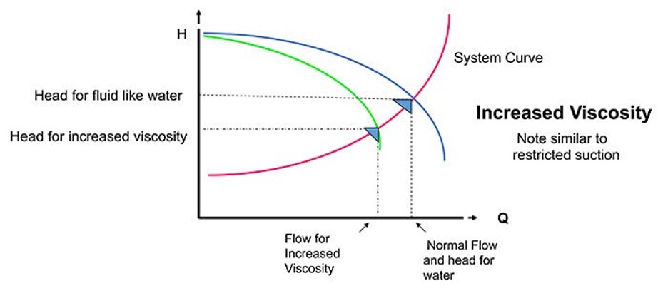
Image 2. Performance effect with increased viscosity

Insufficient NPSH Margin

Pumps require a certain amount of NPSH to operate satisfactorily at a given point of head and flow on the curve to prevent cavitation. The points are empirically determined by the manufacturer and are denoted as net positive suction head required (NPSHr).

The suction system itself must in return provide a certain amount of NPSH, and that is referred to as net positive suction head available (NPSHa). There must be more NPSHa than NPSHr for the pump to operate satisfactorily. The difference is referred to as the margin or ratio.

NPSHa ÷ NPSHr = margin ratio
NPSHa – NPSHr = margin
Equation 1

Refer to Hydraulic Institute 9.6.1-2017 for details.

A frequent field issue is that the margin calculations were not done, not done correctly or there were changes in the pump and/or system that have not been accounted for. A common issue in the field is that the pump has sufficient margin at lower flows, but as the flow rate increases the pump will begin to cavitate. See Image 3 to see how insufficient NPSH margins affects pump performance.

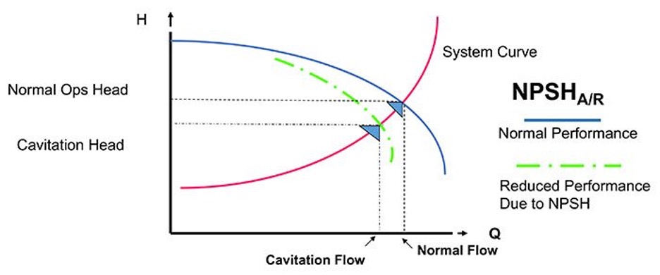
Image 3. Insufficient NPSH—pump will cavitate at higher flow rates (compare to Image 5 restricted flow)

Inadequate Submergence & Air Entrainment

The pumped fluid could have air entrainment from different sources for many reasons, but a common cause is insufficient submergence.

No matter the source of the air, standard centrifugal pumps cannot handle it well. At about 3 to 4 percent air entrainment, the pump performance will drop off as if the impeller was trimmed to a smaller diameter or the pump is being operated at a lower speed.

Please refer to my April 2016 and December 2017 articles for details on air entrainment and pump performance.

Also note that at low flow rates the fluid velocity is insufficient to “sweep away” the air that collects in the impeller eye. Consequently, the pump will become blocked (air bound) and will stop pumping or it will surge in a destructive and alternating cycle of air blockage and subsequent flow passage.

See Image 4 to see how air entrainment de-rates the pump performance.

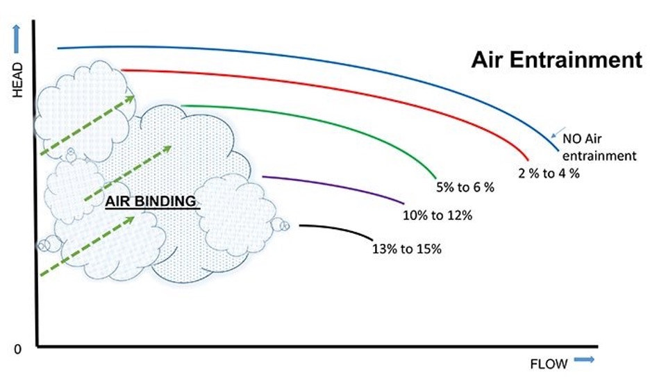
Image 4. Effect on pump performance with increased air entrainment

Restricted Pump Suction

This issue typically manifests on new construction, post repair startups and when there is equipment installed in the suction line like a filter press, foot valve or strainer. As flow increases the head will drop off. This is similar, but different, than an NPSH margin issue.

See Image 5 to see how a suction restriction affects the pump curve.

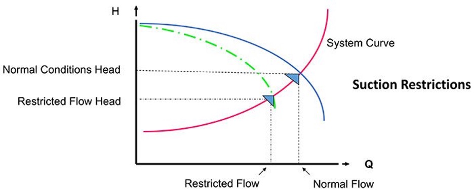
Image 5. (left to right). Effects of suction line restriction. Actual performance will vary with the magnitude of the restriction.

Wrong Direction

I have written about pumps operating in the wrong direction many times because it is unfortunately an all too common issue. In the case of ANSI pumps (with impellers that thread on the shaft), the pump will, 99 percent of the time, pronounce in a millisecond that the direction is incorrect as the impeller grinds into the casing creating expensive and extensive damage and yet hopefully tripping out the motor.

For pumps that have impellers keyed to the shaft it may or may not be obvious. Pumps running backwards will typically be a little noisier and exhibit higher vibrations than a similar pump operating in the correct direction. But this is not always easy to determine in an operating plant due to background noises and other field interference.

Performance will depend on the pump design and is mostly, but not always, a function of the impellers’ specific speed. As a general rule, the flow rate in a reverse operating pump will be about 50 percent, and the head will be somewhere near 60 percent. The higher the impeller specific speed, the lower the head will be. Concentric casing designs will yield different results.

Please see Image 6 to see how reverse rotation may affect pump performance.

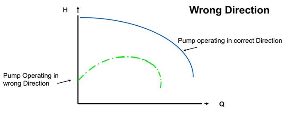
Image 6. Effects of running the pump in the wrong direction. Assumes low- to mid-range specific speed. Do not confuse with pumps running as turbines.

Conclusion

Pumps will operate where the system curve dictates, but the pump curve is not always where you think it is and neither is the system curve. You will not get the performance you need and want by just wishing and hoping—you need to measure the parameters and manage the system.

-Jim Elsey


MYTH: Factory Supplied Pumps are “Plug and Play”

MYTH: Factory Supplied Pumps are “Plug and Play”

Pumps shipped from the factory are NOT ready to be started when and as received in the field.


As an annual ritual I am compelled to remind pump industry people that 99.35% (approx.) of industrial centrifugal pumps do not arrive ready to run and play – unfortunately this “Plug and Play” pump industry myth continues to  persist.

Overview

  1. There is NO OIL in the pump.
  2. The impeller may or may NOT be set to the proper clearance.
  3. The driver is NOT aligned to the pump.
  4. The direction of rotation on the motor has NOT been determined.
  5. The mechanical seal is NOT set.

If you already know these 5 things and fully understand the significance, then you can stop here. If you don’t know or would like a refresher please read on.

Oil
A pump shipped from the factory will NOT have oil in the bearing housing. Someone at the site must add oil prior to startup.

Oil is considered a hazardous substance in the commercial shipping world, consequently it is a violation of several federal laws to ship oil in the pump… Yes, there are means and methods to overcome this issue, but it requires special shipping, more money and paperwork. Additionally, OEM pump manufacturers are not in the business of stocking the multitude of different oils that a customer may request.


Impeller Clearance

A pump shipped from the factory may or may not have the proper axial clearance when it arrives on site. The factory adjusts the clearance at a nominal setting for the pump type and size based on ambient temperature water specifications.

The factory does not know the liquid’s temperature or other properties for the operating system. Note: it is also very possible the settings could have been adjusted after it left the factory. Confirming the clearance in the field is both easy and a professional best practice. Why take the chance? Also, prior to running the pump is the perfect time to take the initial total axial movement readings for the maintenance records.

Alignment

The driver will NOT be aligned precisely to a pump shipped from the factory. The factory utilizes laser manufactured templates for layout and performs a series of nominal checks to ascertain that the motor can be precisely aligned to the pump. Even if the factory did align the driver to the pump in accordance with the highest standards… as soon as the skid is picked up/transported the precision alignment will morph to unacceptable levels.

To learn more about about pump alignment, please check with your regional sales manager or refer to my articles on this subject:

Does Your Pump Have an Alignment Problem?
19 Tips and Common Alignment Mistakes


Driver Direction of Rotation
A pump shipped from the factory will NOT have the coupling spacer installed because you must first complete the driver rotational check with the coupling (spacer) removed. Additionally, with the coupling removed the process to set the impeller and mechanical seal is simplified.

The factory has a 50/50 chance of guessing the correct electrical phase rotation at your local site. If the rotation is wrong, the pump quickly converts to an expensive pile of useless scrap metal shortly after startup.

Mechanical Seal Setting
Factory installed mechanical seals will NOT be set. The pump comes with the seal clips in place (sleep position) to ostensibly preclude damage to the seal during shipping and handling. Plus prior to setting the seal the impeller clearance will need to be checked/set and the alignment completed.

Summary

☑ Read the instructions
☑ Add the oil
☑ Set the impeller clearance
☑ Complete the alignment and rotational checks … then set the seal
☑ Install the coupling spacer and the OHSA guard

Need some assurance when commissioning your pump? Give your RSM a call and/or perhaps review this article on the subject:

The Basics of Pump Startup

Finally
A warning tag is attached to each pump to communicate these 5 key steps to the end user/installer. Of course these steps have always been stated in the Instruction and Operations Manual (IOM). The IOM is included with every pump and if misplaced can also be downloaded from our website.

-Jim Elsey


Why Are There Holes in My New Impeller? Part 3

Common Pumping Mistakes

Open Impellers

True open impellers are not commonly used in industrial pumps because the demands of service require sufficient vane support (webbing or shrouds) to buttress the required torque loads and to maintain the relative geometric position of the vanes.

Be aware that sometimes the vanes on open impellers will move over time and service due to material stress relief issues and other operational force factors. This tendency to move (aka, spring) normally makes them unusable for robust applications. On the positive side, because there is no shroud or webbing either front or back on a true open impeller, there is little to no surface area for the pressure to act on, so minimal axial force is generated.

Semi-Open Impellers

American National Standards Institute (ANSI)-style (B73.1 / B73.2) and International Organization for Standardization (ISO)-style (5199/2858) pumps are single-stage end suction types that use semi-open impellers 98.5 percent of the time (author’s unsubstantiated estimate). Note that there are scores of end suction pump models using semi-open impellers that are not designed to ANSI or ISO specifications such as industrial stock and process pumps.

Semi-open impellers have a shroud on one side only. The simple geometry of this construction makes these impellers less expensive to manufacture. Semi–open impellers also possess the ability to pass through more and larger solids including stringy and fibrous materials than closed impellers.

Typically, an enclosed impeller is more efficient than a semi-open impeller of similar geometry, but it is possible for a semi-open impeller, held to a very tight casing clearance setting (aka, leakage) to be as efficient as a closed impeller, at least for that length of time before the effects of wear open the clearance.

High vs. Low Specific Speed Impellers

Axial flow pumps with impellers of high specific speed will not incorporate shrouds or web supports between the vanes and the impeller will appear more like a boat propeller than an impeller. Do not confuse these with open-style impellers in the low specific speed ranges.

The consequence of the semi-open design is an impeller with higher unbalanced axial forces when compared to a similar size in the fully closed designs. Under normal operating conditions, there will be a much higher force on the back of the impeller than on the front. The resultant force exerts in a direction toward the suction and the pump’s thrust bearing counteracts that force. Please note that even in normal operation, there can be momentary forces acting in either direction, so the thrust bearing should be designed/selected to handle forces in both directions.

A new medium-sized ANSI pump will develop upwards of 850 pounds of axial force and as the pump wears that force increases. The axial force will be reduced proportionally as the suction pressure increases. These factors and more must be considered when calculating the required bearing size and design life span. A typical ANSI pump thrust bearing is nominally designed for a minimum of 17,500 hours.

A pump designer could simply install bigger thrust bearings and not otherwise address the axial force, but the bigger bearings require bigger shafts and that requires bigger frames and housings—all of those things result in a pump that has a bigger initial cost and a higher maintenance cost.

The more practical method used to reduce the axial thrust on end suction pumps and semi-open impellers is to reduce the axial force on the rear shroud by reducing the pressure. This is why the incorporation of balance holes, pump out vanes or both comes into play as axial force reduction methods. Pump out vanes are a design compromise and so there is a small, but acceptable, trade-off with efficiency and power consumption when using this approach.

IMAGE 1: Pump out vanes are small vanes on the backside of the impeller shroud. (Image courtesy of the author)

Pump Out Vanes

Pump out vanes are sometimes simply referred to as POVs, expellers, back vanes or back ribs and are just what the name implies: they are small vanes on the backside of the impeller shroud (Image 1). Pump out vanes are probably the most cost-effective method of axial force reduction.

As previously stated, the main purpose for pump out vanes is to reduce the pressure behind the impeller. Reducing the pressure in this area reduces the axial force pushing the impeller toward suction. The function of pump out vanes is similar to standard impeller vanes in that they impart a velocity to the fluid contained in the annulus area behind the impeller.

As the impeller rotates, the liquid that is adjacent to the impeller shroud will also gain velocity due to the simple phenomena of disc friction. Adding the pump out vanes to the rear shroud simply enhances the desired effect by increasing the angular velocity of the liquid. Increasing the liquid velocity reduces the pressure on the shroud and, therefore, the magnitude of the axial force.

A.J. Stepanoff conducted research and developed formulas based on his experiments with pump out vanes in the 1950s and ’60s. He determined that the angular velocity of the liquid in the annulus area will be about 50 percent of the impeller shroud speed (and pump out vanes). Liquid near the shroud is moving at almost the same speed, but it slows down fairly quickly as you increase the distance from the shroud. Subsequent research has demonstrated that the accurate determination of the true angular velocity is more complicated than my statement, but the basic premise is sound.

One area of contention is the distance from the pump out vane to the stuffing box/seal chamber (think nearest obstruction). The distance defines the axial gap of the annulus chamber behind the impeller. As the impeller moves away from the stuffing box, whether through wear or operator settings, the resultant gap will at some point become too great for the pump out vanes to exert their full effect. Most pump experts agree a performance drop will start to occur when the gap begins to exceed 0.060 inches (1.5 mm).

The pressure-velocity relationship, aka, Bernoulli’s principle: The first law of thermodynamics deals with the conservation of energy and states that energy is always conserved and that it can neither be created nor destroyed, but (and this is the important part) it can be altered in form. A liquid moving in a pipe or a pump casing is in a simple pressure-velocity relationship (energy conservation). If the velocity goes up, the pressure will be reduced and vice versa.

For the general purposes of this column, you can consider the description of pump out vane performance as a simple example of Daniel Bernoulli’s equation and the pressure velocity relationship (with sincere apologies to my Applied Fluid Mechanics 301 professor, Dr. R.G.).

The efficiency and effectiveness of pump out vanes is a direct function of at least six design factors. The first four factors are listed in order of importance:

  1. The radius (length) of the vane
  2. The height of the vane
  3. The number of vanes
  4. The clearance between the pump out vane and the nearest obstruction (stuffing box/seal chamber)

How these factors affect the efficacy of the pump out vanes to reduce thrust is sometimes a subject for debate among pump designers, CFD software developers and engineering researchers. Overlooking some questionable portions of the debate, there remains many aspects of the concept that are agreed on, as follows.

The longer the vane (radius length), the more effective it is to increase the liquid velocity. The caveat is that the longer the vane, the more power is required and it is a function at the fifth power. The bonus is that the manufacturing process of casting the impeller with pump out vanes remains both easy and economical. The height of the vane as it stands out in profile from the shroud (aka, proud) will make it more effective, but at some point you must trade off pressure reduction with the incremental loss of pump efficiency and the inherent increase in power consumption.

The number of pump out vanes is a direct factor in pressure reduction. The more vanes added to the shroud, the more effective the axial force reduction, up to an optimum number of approximately six. Adding more than six vanes will, in most all cases, have no positive effect and so adding a seventh vane will usually be a wasted effort of neutral results. Adding an eighth pump out vane to the design will start to reduce the benefits.

Up for argument: Other pump out vane design factors are the width of the vane and the shape or geometry—think angle, placement and curvature with relation to shaft centerline, i.e., is the vane curved or straight? At this time, the definitive effect of these factors remains both untested and confusing for me. Lastly, often the pump out vanes are where they are simply for economy of production and/or sweeping debris from the space, versus an axial force reduction method.

An additional benefit of using pump out vanes is that the pressure in the seal chamber/stuffing box will also be reduced. This pressure reduction feature works to prolong the life and reduce related costs for the packing or mechanical seal. The reduced pressure effect can sometimes create unintended problems if the product has a high temperature or if the pump is in a lift situation (due to vapor pressure issues).

Either way, there is a higher probability of flashing the liquid to vapor and caution should be exercised. These issues are easily solved with the addition of a flush/seal support system, like a plan 11 or 32, and adding a throttle or restrictive bushing in the bottom of the seal chamber/stuffing box. The portion of the pump world that is governed by API 610 does not endorse pump out vanes as an acceptable method of axial thrust force reduction (API 610 11th section 6.7.1).

Pump out vanes do not increase leakage (bypass) as a balance drum or back ringed impeller would, and they also do not affect the resultant thrust as impeller wear ring clearances inevitably open with wear.

Caution: It is possible to axially adjust the pump shaft such that the pump out vanes are too close to the stuffing box/seal chamber and unintentionally create a vacuum in the annulus and stuffing box area. The vacuum will cause product flashing issues and dramatically shorten the packing or seal life (see remedy above).

Balance Holes

Some impellers will have both balance holes and pump out vanes, others just balance holes or just pump out vanes. Regardless, the reason for the balance holes remains the same, and it is another acceptable method to reduce the axial force and resultant thrust.

Similar to pump out vanes, the balance holes will reduce the pressure in the stuffing box and so, again, be vigilant of the product vapor pressure. It is recommended that you do not use impellers with balance holes in lift situations as the potential for liquid product flashing increases. A lift situation is defined as when the source of liquid being pumped is below the centerline of the pump impeller—that is, the impeller is not flooded. Should the pumped liquid have solids, suspended or entrained, there is risk of clogging the balance holes/passages. Flow from the balance holes will create some level of imbalance and disturbance at the impeller eye, which adds inefficiency.

An impeller with balance holes will make the pump slightly less efficient and require more horsepower to operate. Consequently, the pump is more expensive when calculating the total cost of ownership (TCO). The antithesis is that without the balance holes, the bearing life is shortened.

Operating Tip

The magnitude of axial thrust in a centrifugal pump is a direct function of the differential head. Thus, where the pump operates on its curve will have a direct effect. The further left you operate from the best efficiency point (BEP), the more axial thrust will be generated.

Maintenance Tip

In all of these examples of balancing axial force, it is always important to ensure the pump rotors and impellers are centrally located (both mechanically and hydraulically) in their respective casings/volutes and diffusors. Due to casting variances, machining practices and machine “stack tolerances” (cumulative effect), there may be instances where an impeller will require the addition or removal of a shim and/or some axial position adjustment like a shaft sleeve nut. The purpose of these features is to ensure the rotating mechanical/hydraulic center runs true to the static center of the volute or diffusor. On a new pump, these centering procedure steps were completed during the factory assembly by a knowledgeable technician, but this is also why many better pump designs offer axial adjustment features or suggest and/or support the possible use of shims as required on rebuilds and rotor replacements in the field.

Compromises: Grandma Said ‘You Can’t Get Something for Nothing’

The most efficient and direct method for axial thrust compensation is to simply transfer it to the thrust bearing, which will work in smaller pumps but becomes proportionally expensive as the pump size increases.

Balance drums have a wasteful leakage rate. Semi-open impellers have efficiency robbing pump out vanes, balance holes or both. Cross-over castings are expensive and add another level of complication to the pump. Closed impellers with back rings and balance holes becomes less efficient and more expensive, additionally as the ring clearance increases, so does the axial thrust. Back rings are an added cost, both initially and in subsequent maintenance evolutions, and though seemingly a minor point, they make the pump physically longer.

If you do not purposely design for or add features to balance the axial forces, the thrust bearing will need to be really big, expensive and probably unreliable.

Remember These Two Things

In the end, two things are for sure in the pump world: the laws of physics are strictly enforced, and you can’t get something for nothing.

-Jim Elsey


An Easy Open and Shut Case…

Open or Closed Tanks and the Effect on NPSHA Calculations


When working through NPSHA calculations for pump applications we need to know if the suction supply tank is open to the atmosphere or not. If it is an open tank the calculation is easy; as we just convert the ambient pressure to head for the first factor in the NPSHA calculation. Don’t forget to convert to absolute values and compensate atmospheric pressure for the local altitude above sea level. If the tank is closed, then we need to do a little more work converting the pressure or vacuum to absolute head for the calculation.

The Issue:

Often the customer will tell us the tank is closed to atmosphere, but it really isn’t; consequently the NPSHA calculations will be incorrect. The resulting NPSHA error will lead to a noncompetitive pump selection.

Sometimes the suction supply tank appears to be closed to atmospheric pressure, but if you look closer at the tank you will see it has breather valves installed. If there is a breather valve installed the tank pressure will always be very close to atmospheric pressure. It is very common, especially in the oil and gas world and also in the chemical and petro-chem arenas to use breather valves on the big bulk tanks. You may actually witness these breather valves on any size tank because the owner needs to protect the investment. Please realize these scenarios may also include rail tank cars, but do not confuse these examples with tank cars that are specifically designed to be pressurized or placed under vacuum for unloading purposes.

The Breather Valves Protect the Supply Tanks from:

  • Overpressure (rupture) and or vacuum (implosion) issues
  • Fire protection
  • Evaporation; loss of product
  • Corrosion protection

Another purpose is to prevent excess air and or water (plus other bad stuff like general pollution, Oand NOx) from destroying the product integrity while it is in the tank. The purpose is to protect the product from outside influence and or to protect the outside environment from the product.

These protection/breather valves are normally required by EPA and or OSHA …they are not just a good idea, they are often a legal requirement in many product applications. Most tank owners apply the same rules to all of their tanks regardless of the product, tank size or location. Note that both the EPA and OSHA will defer to API 2000 for the selection and sizing criteria for the breather valves.

So…I Just Want to do the NPSHA Calculation, What Now?:
If the tank has a breather valve, the answer is to simply use the local atmospheric pressure for the NPSHA calculations, because the actual tank pressure is going to be very close.

What if There is no Breather Valve and the Tank is Really Closed Off to Atmosphere?:

When you have a closed tank; I recommend you read my two Pumps and Systems articles on this subject from October and November of 2018, where the basics are covered.
https://www.pumpsandsystems.com/how-calculate-npsha-systems-under-vacuum
https://www.pumpsandsystems.com/calculate-npsha-closed-pressurized-system
If after reading you are still in doubt, call your RSM or engineering for assistance.

Last Comment:
Given a pump system with a supply tank open to atmosphere: note that on the suction line to an operating pump it is not uncommon to have a pressure lower than ambient. You may only expect this situation on a pump that is involved in a suction lift, but even for a flooded suction condition the suction pressure at the pump inlet can be at a vacuum. You can accurately calculate the actual pressure (vacuum) anywhere along the line by using Bernoulli’s Equation. Open and shut case… Easy peasy – lemon squeezy.

References:
OSHA 1910.106 July 1985
API 2000 Venting for Tanks 7th Edition 2014
API 12 (49 CFR 195.264)(b)(1) Specification for tanks
API 650 (CFR 132(b)(3) Specifications for large welded tanks
API Bulletin 2521 (Evaporation Reduction)
API Bulletin 2513 (Evaporation Losses)
EPA 40 CFR 112. Note: This regulation does not actually use the terms “aboveground storage tank.” Instead the term “bulk storage container”.
DOT (various/numerous with respect to rail cars)

-Jim Elsey


Why Are There Holes in My New Impeller? Part 1


radial or axial
Common Pumping Mistakes

Ever wonder why some impellers, all sparkly fresh and new from the factory, have holes in them, or why some impellers have those funny mini-vanes on the back side? The short answer is to reduce axial thrust, reduce the pressure in the stuffing box (seal chamber) and to preclude the collection of foreign debris in the annulus (chamber) behind the impeller. You may think that internal pump forces are not important, that the thrust bearing in the pump is really just window dressing and pump operating/running clearances have little to do with any of this. Unless your pumps run trouble free for more than five to eight years between maintenance, perhaps there is something here.

Regardless of size or design, whenever you operate a centrifugal pump, there are always dynamic forces to be managed and collectively known as the “total dynamic load.” The total dynamic load is the summation of all the forces that manifest throughout the pump as either radial and/or axial loads. The pump designer will address all of the forces by incorporating features to manage, reduce and/or eliminate the effects. And of course, as with everything in machinery, computer software and real life, there are always compromises to be made. Grandma always said, “You can’t get something for nothing.”

Radial or axial
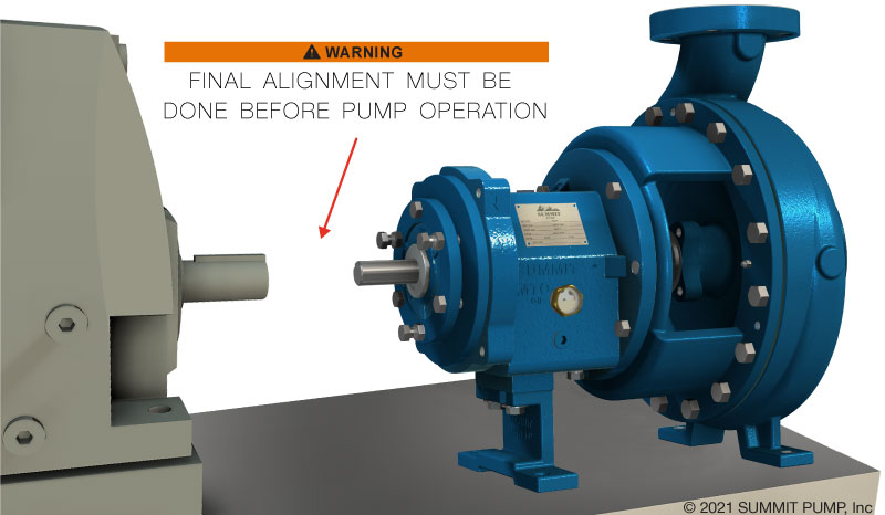
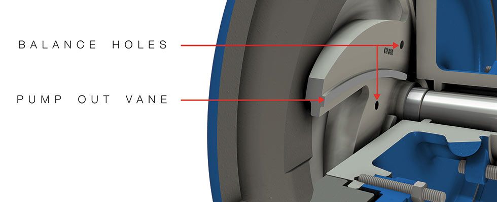
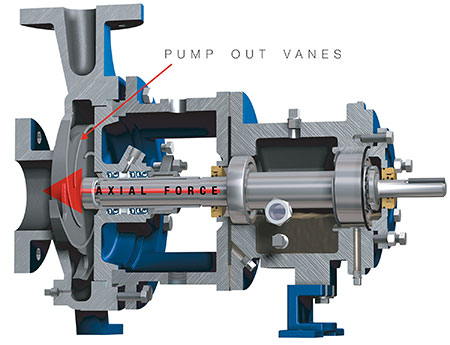
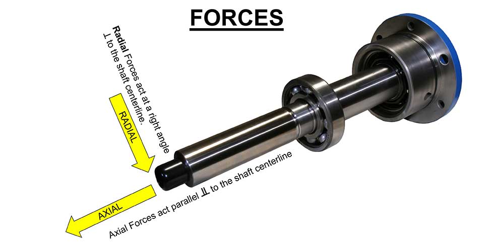
IMAGE 1: Radial or axial, the resultant forces are mostly due to the hydraulic pressure acting on the impeller. F=PA. Force is equal to the pressure (P) working on the effective surface area (A) presented by the impeller shroud(s). (Images courtesy of the author)

Axial Force

There are several dynamic factors that must be addressed in the pump, but the two important ones are the axial and radial forces. This column will address the management of axial forces in the pump. We will look at radial forces in a future column. The actual magnitude of these forces is calculable, but we will skip over those formulas this time and just address the cause and effect.

Axial forces are those that act on the rotor in a direction parallel to the shaft. Axial force, if not properly addressed, will try really hard to push the rotor out one end of the pump. In reality, there are forces acting in all directions on the rotor, but it is the vector summation of the axial components that is our concern for now.

Force (F) as defined for this application, is the total summation of the pressure applied per unit area. Therefore, the higher the pressure and/or the larger the area, the greater the force. The fundamental equation is F = PA; where P = pressure and A = area. This force is also a vector and so it has properties of both magnitude and direction.

The resultant axial forces in the pump exist due to higher pressures acting on one side of a surface and/or acting on a larger surface area when compared to the opposite side. The major thrust contributor in the pump is the pressure working on the large surface areas presented by the impeller shroud(s). But realize that shaft shoulders and impeller hubs also present surface areas and even the small diameter at the end of the shaft (protruding out of the pump at the coupling end) has atmospheric pressure pushing on it.

Pump out vanes are one method to manage axial force.

IMAGE 2: Pump out vanes are one method to manage axial force.

In every case involving axial thrust, the magnitude will be proportionally reduced by an increase in the suction pressure when compared to atmospheric, but of course at some point the suction pressure can be too high for the pump casing or related components such as the packing or mechanical seal. After balancing or reducing most of the axial forces in the pump, the residual axial forces will still need to be carried by the thrust bearing. The thrust bearing transmits the axial force to the pump frame housing and eventually to the foundation.

As hypothetical design questions, ask yourself what type and size of thrust bearing would you put in the pump, and then ask how long do you want the bearing to last? Finally, if the thrust force doesn’t have a pump foundation to transfer to, where does it go?

Methods to Manage Axial Forces in the Pump

There are several methods used in modern pump design to both mitigate and address the effects of axial force. Each approach has positive and negative attributes. Not all methods are covered in this column.

The pure mechanical approach simply designs the thrust bearing to absorb all of the thrust.

Next, there is the hydraulic configuration approach that attempts to reduce the thrust as much as possible via the basic pump design. For example, a back-to-back impeller pump where thrust is balanced due to symmetry. Other methods employ design features and balancing devices that address the forces by using balance drums, balance passages (holes), back ringed impellers, pump out vanes or some combination of these methods. Regardless of the approach in the real world, the pump will still require a thrust bearing of some type and size because no pump (or system) is perfectly balanced over the full range of operations.

Vertical Pumps

Vertical pumps, like the turbine style, will typically use a thrust bearing in the motor that is designed to carry all of the axial thrust from the pump. This is a unique design feature compared to all other types of pumps. There are exceptions were the pump thrust bearing is incorporated into the pump support housing.

Most vertical pumps will have all of the impellers arranged in the same direction. There are industrial grade multistage process pumps that will incorporate a crossover component so that half (or some design mandated percentage) of the impellers are facing one way and the remaining face the opposite direction. A few designs will also incorporate a double suction first-stage impeller.

This column is not covering all types of vertical pumps, and I will not address vertical submersible or cantilever pumps.

Within the normal range of operating conditions, a vertical pump will experience a resultant downthrust, which places the pump shaft in tension. The rotor is designed to be in tension and will experience issues when it is not. Consequently, if there is an upset in pump operations where an upthrust condition overcomes the downthrust for any length of time, there can be serious problems including bearing damage and shaft breakage. Most vertical pump rotors and the motor thrust bearing are designed to accommodate momentary thrust upsets that occur during startup and shutdown.

During normal pump operation, the magnitude of the thrust factor varies with the impeller design, the number of stages, the length of the pump, where the pump is operating on its performance curve and the head generated per stage. Some impellers are hydraulically balanced and some are not, and on some pumps it is a simple option for the application engineer to select on the build sheet to choose either. Consequently, the feature of balanced impellers needs to be declared to all the cooks in the kitchen, especially when choosing the driver and the thrust bearing.

It is both important and prudent to discuss all of these details with the manufacturer and/or an expert in the matter prior to changing where and how the pump will operate. Something as simple and unexpected as changing the type of bowl bearing, radial line shaft bearing or a change in the axial clearance setting (lift) could affect the success or failure of the pump application.

Vertical pumps: locating the pump thrust bearing in the motor makes for a more unique (less interchangeable) and expensive motor. On the pro side of the pros and cons list is that the motor is specifically designed for the application.

Vertical pump impellers typically do not use pump out vanes (for thrust reduction) in the majority of designs because of axial clearance uniformity issues when setting the pump rotor lift (short version is variance and stack tolerances), but many designs have the option to incorporate balance holes in the impeller(s) to reduce the thrust.

-Jim Elsey


What’s the speed limit?

How fast was I going officer?


Speed is a critical limit for any pump, but even more so for Positive Displacement (PD) pumps. The maximum allowable speed of a PD pump is determined by several factors including the viscosity and temperature of the pumpage. Other important factors are the level of abrasives in the product, acceleration head, and the Net Positive Suction Head Required (NPSHR).

Commercially available and cost effective electric induction motors nominally operate at speeds well above the optimum PD pump speeds, consequently some method must be used to reduce the drive output speed. Direct drive is just not all that common in most Internal Gear Pump (IGP) and Progressive Cavity (PC) applications for this reason.

The boundary for PD pump speed will typically be managed with either a gear reducer or a Variable Frequency Drive (VFD) and/or a combination of the two. For even more precise flow modifications a servo motor can be used in conjunction with both a gear reducer and a VFD.

Speed Kills

As the product temperature and/or abrasive concentrations increase, the pump should be operated at even slower speeds to reduce the inevitable wear and increase reliability. This may also mean a bigger and slower pump is required. Pump wear is exponentially proportional to speed. Even for relatively small increases in speed the wear rate can increase by a factor of eight.

Prior to purchase, the allowable speed range for the pump should be reviewed so that the correct choice of materials and speed control are made to achieve the lowest Total Cost of Ownership (TCO) and Mean Time between Failures and Repairs (MTBF/R).

Controlling Speed

Gear reducers (aka “gear sets” or “gear boxes”) are both essential and common components in the drive train of many PD pumps. Unfortunately the fixed output of a gear box will lock the end user into one operating speed. Therefore, the pump’s hydraulic duty point (at some speed) and the maximum allowable speed must both be considered when making the selection.

One additional benefit of a gear reducer is the increase in the amount of torque delivered to the pump shaft.  Gear sets are frequently referred to as “torque multipliers” for this reason. Adding a gear set may potentially reduce the required motor size when compared to direct drive.

VFDs are often used in applications where speed dependent flow requirements will/can vary over a range. A VFD in conjunction with a gear reducer will allow the pump to operate across an acceptable range of speeds, while simultaneously providing the required proportional flow rate.

Note: Pump speed limits must be applied when initially programming the VFD.  The VFD operational parameters must be set within the pump’s speed limits to avoid the critical and common over speed mistake. 

Don’t get Pulled Over by the Pump Police for Speeding: 

Operating correctly saves time and money.

Teaching owners and end users about pump boundaries allows them to choose smart solutions for their application and ensure the equipment is effective, efficient and reliable… reducing the TCO and MTBF/R.

If you have any questions please contact your Regional Manager or Engineering in Green Bay.