Case Studies
Our solution will save a customer over $80,000 a year for just ONE drying operation.
Big savings by less compressed air usage for drying parts
 SITUATION
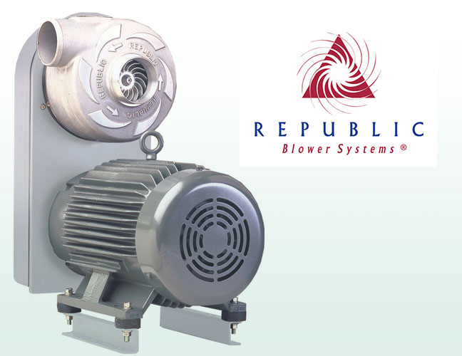
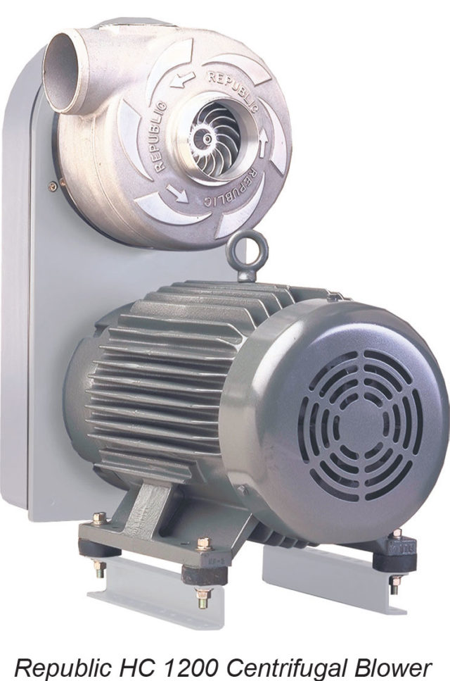
Compressed air is often referred to as the “third utility” in industrial plants as the cost to produce it can be extremely high. Many companies use compressed air to blow off or dry parts during certain stages of the manufacturing process. Large air compressors are expensive to purchase and maintain not to mention the cost of compressed air delivery equipment (ie, high pressure hoses, air knives, blades and nozzles, etc.) used to get the air to the process. R.A. Ross and Associates was able to bring an air savings solution to a major brake pad manufacturer in Kentucky by recommending the use of regenerative air blowers instead of compressed air to dry parts. Regenerative air blowers produce a higher volume of air at a lower pressure at the same time using less energy. The cost savings to the customer by switching to the regenerative blower and air knife system for one drying operation came to approximately $80,000 per year*. Equipment payback was about 9 weeks. That’s a serious solution! And at R.A. Ross & Associates, that’s what we do everyday!
HOW IT WORKS
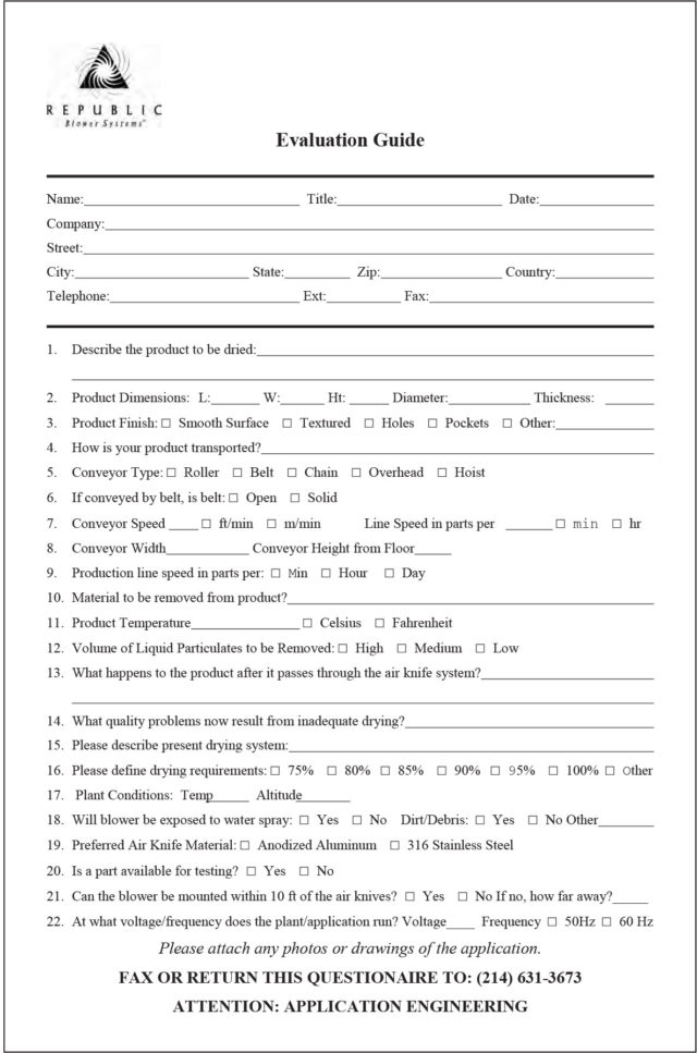
Since each product and application is unique, Republic Blowers will ask that you fill out an Evaluation Guide (example below) detailing size of product, description of product, (holes, shape, etc.), speed of conveyor belt and so on. Once your specific need is determined, a custom designed air knife system will be recommended. Once approved, we will then test and be able to determine the amount of savings over traditional compressed air operations.
REPUBLIC MANUFACTURING AIR KNIFE SYSTEMS
• Custom designed and manufactured
• Perfect for: Drying parts, bottles, cans, food products, packaging,fruits, vegetables, meat, fish, poultry, textiles, carpet,film, wire, cable, metal, tile, wood, flooring
•Belt cleaning: Debris removal, sawdust removal, confectioner and food topping removal, liquid blow-off
•Static control
•Air curtain: Prevent hot air loss from oven, prevent cold air loss from freezer
Over $80,000 per year compressed air savings!
Featured, Resources, Summit Pumps
 “Your pump isn’t producing enough flow!”
“I can’t get enough pressure out of your pump!”
“Your pump is making noise!”
We often get these calls from the field. While it is entirely possible, in reality,
it is rarely the pump’s fault.
From my almost fifty years of field experience with pump troubleshooting; I’ve found almost 80 percent of all centrifugal pump issues are on the suction side of the pump. I always start looking there first.
Key Data Needed, Prior to Calling Factory or RSM:
- Pump serial number.
- Fluid properties, or as I like to call it the “fluid personality”. (Temperature / Vapor Pressure / Specific Gravity / Viscosity / Suspended Solids / pH
- What condition was the pump sized for? Flow and head (differential head)
- What clearance is the impeller set at?
- What is the Shutoff pressure?
- Duty Cycle
- NPSHA?
- Submergence?
- Is the pump suction condition in a lift or flooded situation?
- Perhaps supply a sketch or photos of the system showing pipe size, elevations and components. “A picture is worth a thousand words”
- New application or replacement? If it’s a replacement pump, ask why they are replacing it.
The above data should be fairly quick and easy to get from the customer, using a Summit Pump Application Data Sheet. If you cannot solve the problem based on the above data, below are some more in-depth items to investigate further:
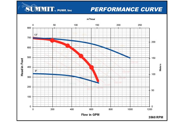
Sketch your pump’s performance against the Summit Pump performance curve.
Further Investigation:
- Confirm pump speed (RPM). This can be done with a tachometer. Be on the lookout for VFD issues, belt or engine driven installations.
- Confirm direction of rotation.
- Proper suction piping per ANSI/HI 9.6.6 guidelines. Proper pipe diameter, length and orientation is critical to successful pump/system operation
- Check the suction source. Is the tank too small, causing turbulence and high velocity? Is there entrained air in the liquid? Is there proper submergence?
- Gauges. Are the proper gauges installed? Are they calibrated?
- Suction lift conditions. Is the lift too high? What is the vapor pressure? Air leaks?
- Head & NPSHa Calculations. Confirm the head & NPSHa calculations. What is the NPSH margin? If the calculations are incorrect, the pump could be incorrectly sized for the application.
- Confirm liquid properties. Is the given information actually the liquid they are pumping? Did the process liquid change? (Specific Gravity, Viscosity, Temperature, Vapor Pressure)
- Pipe Strain. Is the piping properly supported? If not, pipe strain will usually manifest as hot bearings and alignment related issues. Was it laser-aligned?
- Parallel or Series Pumping. If not installed/operated correctly, pumps operating in parallel or series can have problems, and the pump(s) might not perform correctly.
Next Steps:
If you don’t know how to investigate these issues, and/or you are simply not comfortable with the process, we can assist, but please know that we are not system designers.
Case Studies
Problem:
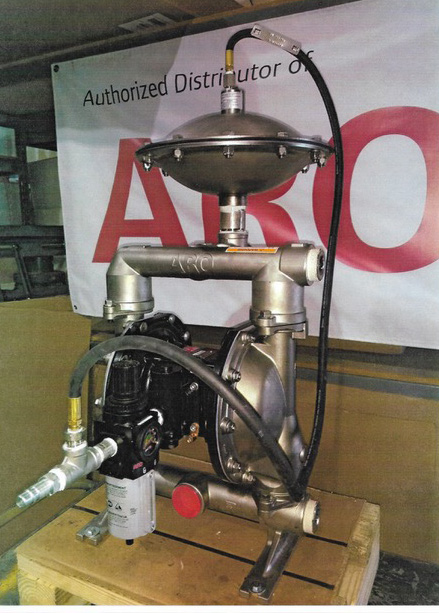 A major chemical manufacturer in Southern Indiana was having an issue with premature diaphragm failures on a chemical transfer operation.
The diaphragms in a competitors air operated double-diaphragm (AODD) pump were failing after only a short time in operation.
In this harsh application, the pumps are required to transfer chemicals from totes to other process-es in the plant. The operators must work quickly between batches and the pumps are required to pump several different chemicals each day.
After visiting with the customer and seeing the operation, it was surmised that the reason for the premature diaphragm failures was over-pressurization on the air supply and water hammer or back pressure spikes from the rapid opening and closing of valves at the beginning and end of pumping cycles.
Solution:
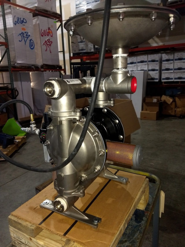 Our team came up with the following solution; we recommended a custom package comprised of a 1.5” ARO® AODD pump in 316SS and Teflon construction with ARO® Long Life® Teflon diaphragms, an ARO® air line kit complete with air hose, air pressure regulator/filter with gauge and a 1.5” NPT, 316SS/Teflon pulsation damp-ener manufactured by Blacoh®.
Additionally, this equipment was offered on a 60-day trail basis. The customer has experienced a significant increase in diaphragm life with this system in place.
If you have a troublesome application, let us provide a solution for you!
Custom diaphragm pump package model info:
- 1.5” ARO®, air-operated, double diaphragm pump model PD15A-ASS-STL
- ARO® air line connection kit w/ARO® filter-regulator and gauge for air pressure control
- 1.5” Blacoh® pulsation dampener model AOD-15-NPT
Featured, Resources, Summit Pumps
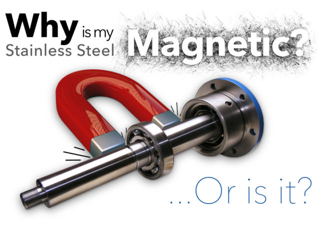
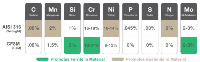
Several times a month we receive an inquiry from a concerned customer that the “stainless steel” they received from Summit Pump is magnetic and/or appears to be rusting.
We assure them there is no issue, and explain as follows.
In the case of plain/standard 316-SS, it is usually because the piece has been cold worked and will pick up some magnetic properties. Note if you were to compare the 316-SS to a 400 series stainless you would see an increase in magnitude of the magnetic attraction. It will not attract other ferritic metals, only the magnet, as a result the material itself is not necessarily magnetic, it is ferrous. The magnetic response has no effect on any other property. Austenitic 300 series steels like cold drawn 304 (and to a lesser degree 316) are slightly attracted to a magnet, but this has no effect on its corrosion resistance.
Cold Working: Parts that are highly worked (due to machine operations), such as sleeves and shafts that have been machined, ground and polished, will lend themselves even more to this phenomena.
Corrosion:In 316-SS it is the chrome content that makes it stainless, but it is the nickel content that makes it nonmagnetic.
In the process of cleaning the materials at the foundry and the machine shop, there could be some residual ferrite (iron) from the cleaning process which temporarily alters the surface. The surface may become contaminated on the work site as well. The remedy is to pickle and passivate the surface once again. Stainless surfaces must be kept clean, so the surface can generate the passivation layer and remain as new. It is the chrome oxide film that stainless naturally forms that keeps it from corroding.
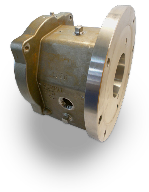
Rolled or Cast: There is a difference in cast stainless steels versus wrought stainless steels that aggravates and differentiates the issue of magnetic attraction. In the case of cast stainless steel, like CF8M, the chemistry and micro structure are purposely different from rolled steel, but the physical and corrosion properties are similar. AISI 316-SS is wrought steel and is notably less or nonmagnetic altogether, as compared to CF8M.
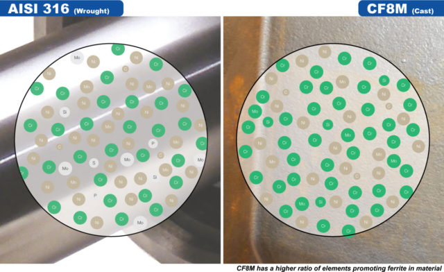
We want some ferrite in the CF8M cast steels to increase the strength and increase its resistance to corrosion cracking. The small amount of ferrite also reduces some forms of corrosion and helps with weldability.
Duplex and Super Duplex Materials: CD4MCu is a duplex stainless steel with magnetic attraction, due to its ferrite content.
If you remain concerned about the material’s magnetic properties, please discuss with engineering or your RSM. It’s possible to perform and document a witnessed PMI test at no charge.
-The Summit Pump Team
Learn More
Jim Elsey’s Pumps and Systems Articles
Featured, Resources, Summit Pumps
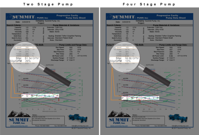
Fluid slip is a common term used to describe reverse fluid flow inside a pump or other turbomachinery. Slip is affected by 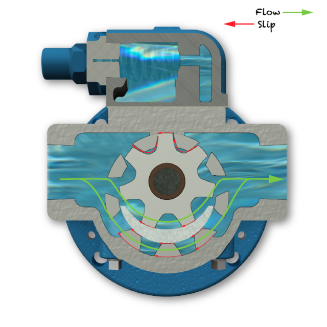 internal clearances of the parts, temperature, pressure and viscosity.
In a positive displacement pump, slip can be easily calculated just by looking at the flow being produced while in operation and subtracted from the nominal flow rate of the pump per one revolution.

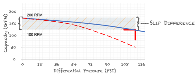
Another way to determine the amount of slip is looking at the pump curve. At 0 psi, the pump is producing its nominal flow at the RPM. Notice as the pressure increases running at the same RPM, the flow will decrease. The difference between the operating pressure and 0 psi is the amount of fluid slip the pump is experiencing. This method is more of an approximation whereas the above measured flow minus the nominal flow per revolution is more accurate.
Why Should we Care About Slip?
Most importantly, too much slip can increase wear and decrease pump life, especially if the fluid is abrasive or has solids. Abrasive fluid passing through the clearances of the internal parts has the same effect of sand blasting. This opens up the clearances even more, amplifying the issue.
Next, too much slip can increase the cost of operation and loss of efficiency. In a positive displacement pump, if you are not getting the desired flow rate the first thing you do is turn up the speed, but doing this also increases the required power needed to meet same flow and pressure.
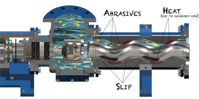
Excessive amounts of slip will introduce heat into the pump. This is critical in both the Progressive Cavity and Internal Gear Pump lines. Elastomers in the Progressive Cavity’s stator, or any rubber, has a set life limit based on how much heat it can absorb. The more heat it absorbs, the shorter its life.
The clearances in the Internal Gear Pump are extremely tight and with extra heat introduced can cause the rotor and idler to expand and potentially lock up against the head or casing. As a side note, if the safety relief valve is being used as a flow throttling mechanism, it can also cause the rotor and idler to expand as well.
How do you Decrease Slip?
When sizing positive displacement pumps, our guidelines is to keep slip under 15% of the desired flow rate. One option to achieve this is to choose a smaller pump, but keep in mind RPM restrictions. When sizing Progressive Cavity pumps, our guideline is nothing faster than 300 RPM, to minimize the amount of heat generated to maximize stator elastomer life.
 “Summit Pump Man,
I don’t want to change my existing pump size,
what else can I do to minimize slip?”
Reduce the pressure of the system. Reduce the all unnecessary fittings, increase pipe diameter, operate at a lower flow rate, ensure all filters and pipe runs are clean of debris, shorten the distance the fluid has to run.
A convenient feature of the Progressive Cavity pump is the ability to simply change the stage of the pump. For example, increasing a 2-stage rotor and stator to a 4-stage will reduce the amount of pressure per stage the pump experiences. Ultimately, reducing the amount of slip by a factor of the stage change. As with everything, there is always a tradeoff, torque and power required will increase and resulting factors need to be examined, such as motor size, pump frame size and location space available.
-The Summit Pump Team
Learn More
Jim Elsey’s Pumps and Systems Articles