
How fast was I going officer?
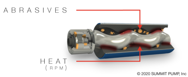
Speed is a critical limit for any pump, but even more so for Positive Displacement (PD) pumps. The maximum allowable speed of a PD pump is determined by several factors including the viscosity and temperature of the pumpage. Other important factors are the level of abrasives in the product, acceleration head, and the Net Positive Suction Head Required (NPSHR).
Commercially available and cost effective electric induction motors nominally operate at speeds well above the optimum PD pump speeds, consequently some method must be used to reduce the drive output speed. Direct drive is just not all that common in most Internal Gear Pump (IGP) and Progressive Cavity (PC) applications for this reason.
The boundary for PD pump speed will typically be managed with either a gear reducer or a Variable Frequency Drive (VFD) and/or a combination of the two. For even more precise flow modifications a servo motor can be used in conjunction with both a gear reducer and a VFD.
Speed Kills
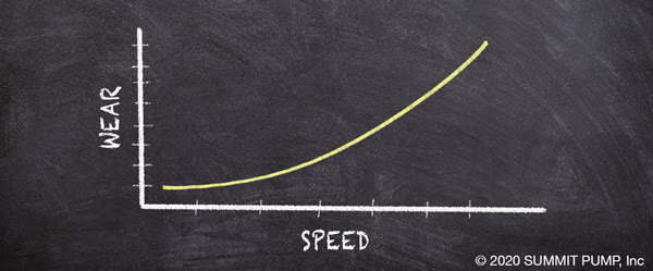
As the product temperature and/or abrasive concentrations increase, the pump should be operated at even slower speeds to reduce the inevitable wear and increase reliability. This may also mean a bigger and slower pump is required. Pump wear is exponentially proportional to speed. Even for relatively small increases in speed the wear rate can increase by a factor of eight.
Prior to purchase, the allowable speed range for the pump should be reviewed so that the correct choice of materials and speed control are made to achieve the lowest Total Cost of Ownership (TCO) and Mean Time between Failures and Repairs (MTBF/R).
Controlling Speed
Gear reducers (aka “gear sets” or “gear boxes”) are both essential and common components in the drive train of many PD pumps. Unfortunately the fixed output of a gear box will lock the end user into one operating speed. Therefore, the pump’s hydraulic duty point (at some speed) and the maximum allowable speed must both be considered when making the selection.
One additional benefit of a gear reducer is the increase in the amount of torque delivered to the pump shaft. Gear sets are frequently referred to as “torque multipliers” for this reason. Adding a gear set may potentially reduce the required motor size when compared to direct drive.
VFDs are often used in applications where speed dependent flow requirements will/can vary over a range. A VFD in conjunction with a gear reducer will allow the pump to operate across an acceptable range of speeds, while simultaneously providing the required proportional flow rate.
Note: Pump speed limits must be applied when initially programming the VFD. The VFD operational parameters must be set within the pump’s speed limits to avoid the critical and common over speed mistake.
Don’t get Pulled Over by the Pump Police for Speeding:
Operating correctly saves time and money.
If you have any questions please contact your Regional Manager or Engineering in Green Bay.