When NOT to use a pump for liquid transfer.

A case study in how to transfer liquified gases (propylene, in this application) using the vapor itself.

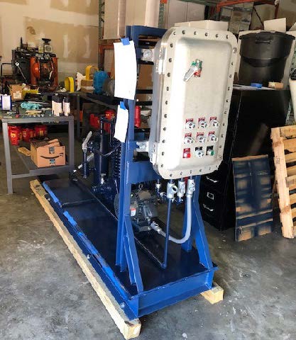
Custom-built, explosion proof Blackmer compressor package exceeded our customers expectations!*

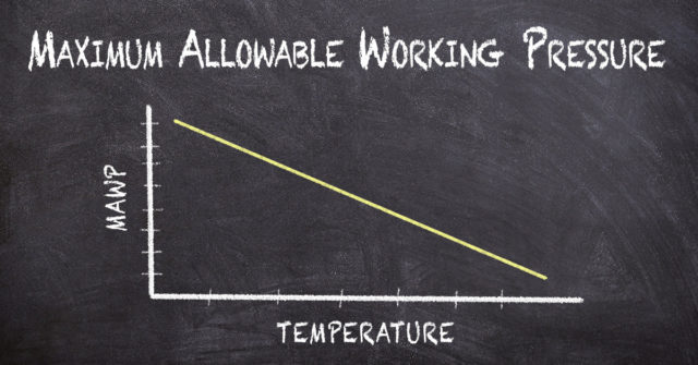
There are challenges when transferring liquids that are vapors at atmospheric pressures. Liquids like ammonia, butadiene, propane, propylene, refrigerants, or vinyl chloride must be contained under pressure to keep them in equilibrium. Pumps, with the limited Net Positive Suction Head available (NPSHA), cavitate and can become vapor locked.

Using Blackmer HD gas compressors to compress the vapor to transfer the product is much more efficient. Transfer faster and recover much more product with the Blackmer HD compressor.

A global chemical manufacturer (and their engineering firm) asked for “Liquid transfer of propylene from a 435 lb. cylinder to a 125 gallon storage tank and transfer from the storage tank to a feed tank”. Conditions: 20F, 57 psi inlet pressure/77 psi discharge pressure; 70F, 140 psi inlet pressure/166 discharge pressure; and 100F, 210 psi inlet pressure/230 discharge pressure thus the compressor was going to see varying conditions although the differential pressures (discharge minus suction) were pretty constant at 20 psid to 26 psid.


Using a Blackmer compressor for liquid transfer and vapor recovery

How it works:

LIQUID TRANSFER

The compressor and 4 way valve is configured to allow the destination vessel vapor to enter the compressor where the gas is slightly compressed and discharged to the top of the source container or vessel where the gas pushes on the top of the liquid forcing the liquid up the liquid line connected to the bottom of destination vessel.


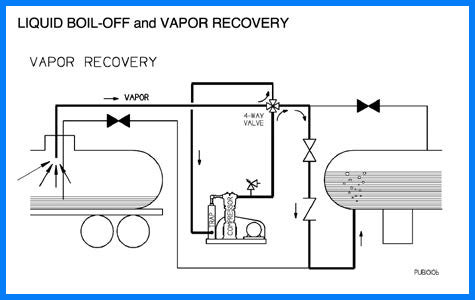
LIQUID BOIL OFF AND VAPOR RECOVERY

When nearly all the product is transferred, you are left with a small amount (heel) at the bottom. You then change the 4 way valve and other valves to allow the vapor line from the source vessel to connect to the compressor inlet and you compress that gas and push it up through the bottom of the destination vessel. As the gas travels up through the liquid, it cools and tends to condense into liquid. This operation continues until the pressure in the source vessel drops to a pre-set point (typically dictated by economics).

The compressor transfer process described is done with many liquified gases and natural gas with the same basic process steps.

As a long-time distributor for Blackmer, we were able to provide a Blackmer gas compressor package for this important application.

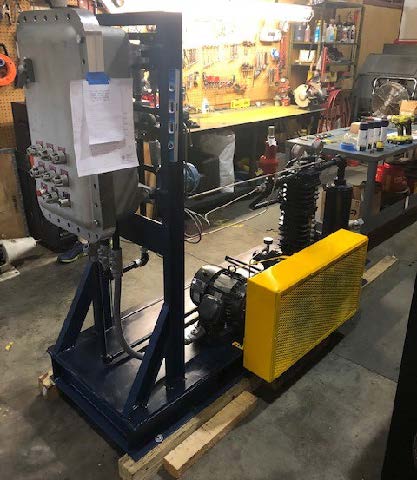
Our design team assembled a complete package in our Louisville facility per the customers requirements from the ground up, including a custom steel base with forklift portability, and a complete controls package for “plug and play” installation.

* Our customer asked for 15 minute liquid transfer and we did it in about 5 minutes! 

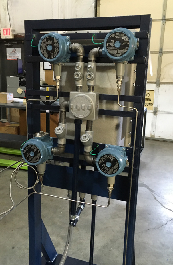
Backside of Nema 7 control panel showing Nema 7 controls which were prewired and connected to compressor and panel.

Application details:

Liquified gas transfer of propylene from 435-gal cylinder to 125-gal storage tank and transfer from storage tank to feed tank. 4 SCFM @ 77 PSIG, 166 PSIG and 231 PSIG.

Custom compressor package:

  • Blackmer heavy-duty compressor model HD082B (Blackmer’s smallest HD size) – non-lubricated, 1-stage, vertical, air cooled, single cylinder, single acting, ductile-iron construction with packing.
  • 76”x26” structural steel baseplate with V-belt drive, belt-guard, motor slide base, liquid trap, 4-way valve and strainer.
  • 3-HP, 1750 RPM, 182T frame explosion proof motor, belt drive.
  • NEMA7 Low oil pressure switch, low suction pressure switch, high discharge pressure switch, high temp switch and SS high liquid level float switch.
  • Discharge relief valve ASME.
  • Mounted and wired NEMA 7 control panel with start/stop push button, Power “on” light, Production test report and hydrostatic test @ 503 PSIG.

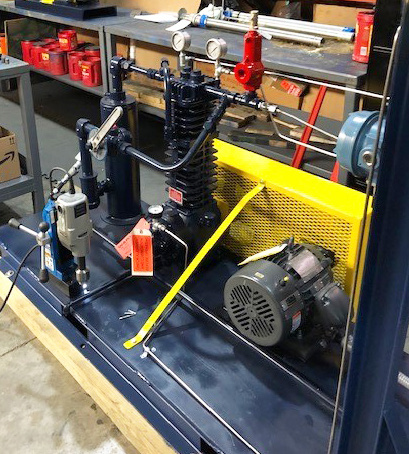
Blackmer heavy-duty compressor model HD082B mounted on structural steel baseplate.


Centrifugal Pumps | An Open and Shut Case?

I am frequently asked; should the discharge valve be open or closed when the pump is started? My answer is….it depends, but regardless the suction valve better be open.


First Things First

Let’s look at the impeller. There are many things to consider, but the primary question we want to answer today is; what is the geometry of the impeller? From that shape we will determine the range of Specific Speed (NS). Ok, I may have lost you now because I used the nerdy “Specific Speed” term, but let me explain. Just for today’s purpose, let’s focus on the directional path of the liquid and specifically how it enters and exits the impeller.

Specific Speed is a predictive indicator for the shape of the curves for head, power and efficiency.

Low Ns

If the liquid enters the impeller on a path parallel with the shaft centerline and exits the impeller at an angle 90 degrees to the shaft centerline (at a right angle) then the impeller is in the low Specific Speed range. This would be a typical radial impeller like the Summit Pump model CC-FM.

Medium Ns

If the liquid enters the impeller on a path parallel with the shaft centerline and exits somewhere close to a 45 degree angle, then the impeller is in a medium Specific Speed range. These are mixed flow or Francis-Vane type impellers.

High Ns

If the liquid enters the impeller on a path parallel with the shaft centerline and exits in a path parallel to the shaft centerline, this is a high Specific Speed impeller. This axial flow type of impeller would look similar to a boat or airplane propeller.

Plan B

Don’t know the Specific Speed (Ns) of the impeller? Ask the manufacturer.


Now for the Really Interesting Part

For low Specific Speed (Ns) pumps the Brake Horse Power (BHP) required increases as you open the discharge valve and increase the flow rate, this is a direct relationship just as you would intuitively expect. For medium Ns pumps the BHP curve and its maximum point moves back to the left some nominal amount … in the past you may have not noticed this change. Axial flow pumps, of high Ns, the BHP is near its maximum point at the lower flow rates and actually reduces as the flow rate increases. Perhaps the opposite of what you would expect? Notice how the slope of the power graph also changes when the impeller design goes from low to high specific speed.

And…Answering the Original Question

I recommend that the discharge valve be closed on the startup of low Ns pumps and to be open on high Ns pumps. Note, this is a “thumb rule” and there are numerous caveats that can and will modify the answer.

  1. If the low Specific Speed (NS) pump is of any consequential size (Flow, Head and BHP) you may need to have the discharge valve slightly open to reduce the differential pressure across the valve. This step will minimize the effort to open the valve. Some pump systems will have a bypass line for this purpose.
  2. Systems that have downstream pressure (from another source) with no check valves (or check valves that are leaking by) can force the pump to spin backwards when the discharge valve is open.
  3. If you are starting a pump that will operate in parallel with another pump(s) you need to consider check valve lift points and controlling instrumentation (PID); this is a subject too cumbersome to explain in the “Sixty Seconds” platform.
  4. Normally, high Specific Speed (NS) pumps are started with the discharge valve open to reduce the electrical load and resultant stresses on the driver. In many cases the driver may not be adequately sized (on purpose) to handle the low flow power requirements and will trip offline.

-Jim Elsey


Pump Testing

It shows that our client/customer base is becoming more sophisticated; because we see an increase in requests for performance tests. Testing is a great opportunity for us to exhibit our integrity and professionalism when our pumps are subsequently proven to meet the published performance data.

If the customer requires pump performance testing, the specific pump test and consequently the acceptable tolerances must be defined. The industry standard specification for our pumps is ANSI/Hydraulic institute 14.6-2011. But note, even within that 75 page specification there are numerous variables, detailed options and tolerance classes that remain to be defined.

The time to have the test, the delivery schedule and the subsequent costs defined is before the order is placed.

-Jim Elsey


Pumps are not “Plug and Play”

I repeat this message annually… no, monthly. No matter the manufacturer; the majority of all pumps do NOT come from the factory ready to start up.

The pump will require oil to be added to the bearing housings.

The impeller clearance must be determined and set for the fluid temperature. The direction of rotation should be ascertained and matched to the phase rotation on the motor driver (you must do this step with the coupling removed).

The driver will need to be aligned to the pump. When I tell people that they should align their pump nine times, I get some funny looks, but allow me to explain. Yes, the alignment may have been performed in the factory, but the very second the unit was moved for transport the alignment was lost. You will need to recheck the alignment when the unit is installed and leveled, again when the base is grouted, again after the piping is installed and again after the pump has been running up to temp.

The mechanical seal will need to be set after the above steps are completed.

Finally… please understand that most manufacturers do not install the coupling at the factory because it will just need to be removed for all the above reasons.

Be ready to complete these items, so you look like a pump professional.

-Jim Elsey


Pumps Have Boundaries

Pressure and temperature boundaries are the most common violations we see in this boundary category. Don’t forget that pump suction pressure is part of the overall discharge pressure calculation.


Note: Allowable pressure limits decrease with increasing temperature and not all materials have the same ratings.

If there is any doubt please consult with us. We can send you a rating chart for both 150 and 300 class flange ratings.
Do not get a ticket from the boundary police.

-Jim Elsey