Featured, Resources, Summit Pumps
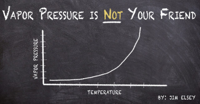
Be very careful on self-primer lift applications because the liquid temperature
directly affects its vapor pressure and that…
…changes the Net Positive Suction Head Available (NPSHA).
 Example: Self-Primer – two temperatures… two outcomes:
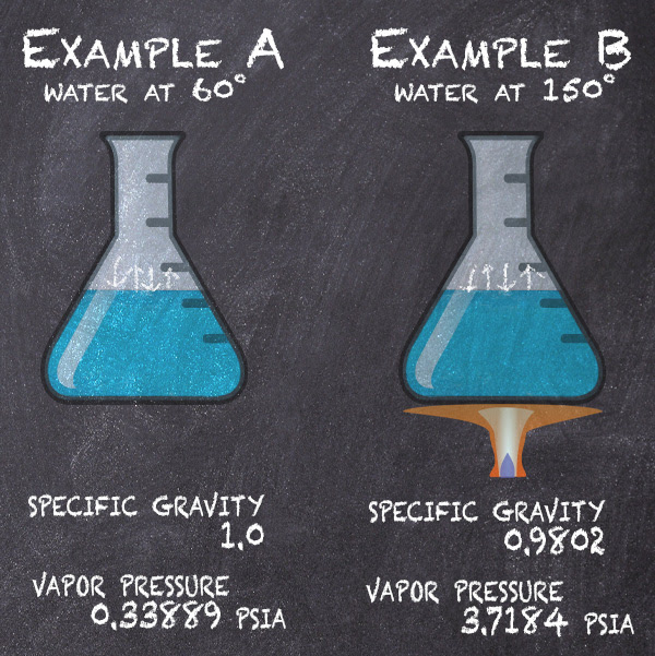
For the example we will use two versions of the otherwise same application. The applications are identical in both versions except the temperature of the fluid is higher in the second version. The higher temperature signifies the vapor pressure has increased.
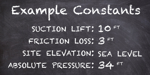
*Note: 14.7 PSI absolute atmospheric pressure x 2.31 divided by the Specific Gravity of 1 = 33.96 feet ≈ 34).
Any increase in elevation will reduce your absolute pressure (head) and consequently the NPSHA.
In Example A the fluid is water at 68ºF.
In Example B the fluid is water at 150ºF.
As you look up the vapor pressure of water for each temperature note it is normally expressed in PSIA (pounds per square inch absolute) and so you need to convert that value to feet (head) then you will have the component value in the proper units needed to do the NPSHA calculation. Remember that to convert PSI (or PSIA) to head, you must multiply by 2.31 and divide by the specific gravity.
You can find these vapor pressure and specific gravity values in several places;
I use the Cameron Hydraulic Data Book or Cranes Technical Publication 410
(There are also several reputable web based sources).
Once you have the conversions then fill in the values for the formula and do the simple math steps (0.33889 X 2.31 = 0.783 ft. and 0.783 divided by 1 is 0.783). Then fill in the values in the NPSHA formula and complete the steps for the answer. Repeat these steps using the different values for Example B.

Note: The difference between the two versions for the value of NPSHA = 7.98 feet which is approximately 8 feet.
Summary: With all the parameters except temperature (vapor pressure) the same and simply changing the temperature of the fluid from 68 to 150 degrees we reduced the NPSHA by 8 feet. This may not seem like a big deal until you realize that the pump requires 13 feet of NPSHR at the condition point and now 12.24 feet is all that is available. The pump will not operate correctly and will be in a constant state of cavitation.
Corollary: Most pump manufacturers do not recommend using self–primer pumps on lift applications above 145°F for this reason. The solution for fluid temperatures above 145ºF will likely involve a vertical sump pump or a submersible pump.
-Jim Elsey
Featured, Resources, Summit Pumps

For those of us living in the northern hemisphere winter is coming and this message will serve both as a reminder and a warning as to the inevitable arrival of temperatures below freezing.
For folks like us who reside in the higher latitudes, we know from experience that at some point in time (someday soon) the temperatures will fall below freezing. Before the freezing temperatures arrive we need to take action regarding those things that could be damaged in the freezing process. Simple things like the garden hose, the swimming pool, a boat or camper, and the forgotten items in the unheated garage/shed; like a pressure washer for example.

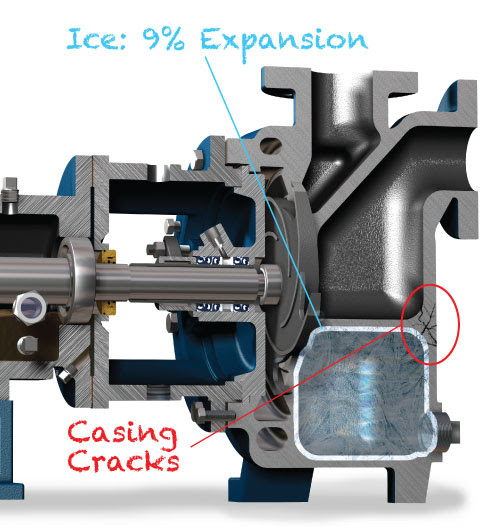
If you or your customers have a pump (and piping) that is not protected from freezing, you need to remove the water or the casing will crack and suffer expensive and permanent damage in the process. If you can’t remove the water then take steps to move the item to a protected area, add some type of anti-freeze, or add heat trace/tape.
 If you live in a more moderate climate, at lower latitudes, where it doesn’t freeze very often you may not think about these things or take any precautions. And this is also the same geographical area where we sell a lot of replacement casings when it does freeze. For some reason self-primer pumps are overlooked more often than other types. I guess because folks forget about the water in the priming chamber.
Did you know that water is one of the only liquids that expands when it freezes? A few solid elements expand when they freeze, but water is the essentially the only liquid that expands due to its crystalline structure. When liquid water is cooled down from standard temperatures, it contracts as you would expect until around 37 degrees F, but then as the temperature lowers below 37 degrees the water expands slightly until it reaches the freezing point. When water freezes it expands by about 9%.
Winter is coming and the nights are long and cold. Will your pumps be ready?
-Jim Elsey
Featured, Resources, Summit Pumps
Open or Closed Tanks and the Effect on NPSHA Calculations
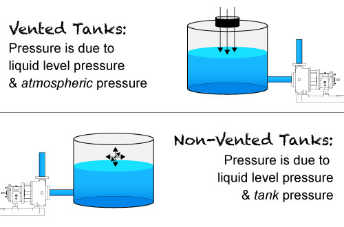
When working through NPSHA calculations for pump applications we need to know if the suction supply tank is open to the atmosphere or not. If it is an open tank the calculation is easy; as we just convert the ambient pressure to head for the first factor in the NPSHA calculation. Don’t forget to convert to absolute values and compensate atmospheric pressure for the local altitude above sea level. If the tank is closed, then we need to do a little more work converting the pressure or vacuum to absolute head for the calculation.
The Issue:
Often the customer will tell us the tank is closed to atmosphere, but it really isn’t; consequently the NPSHA calculations will be incorrect. The resulting NPSHA error will lead to a noncompetitive pump selection.
Sometimes the suction supply tank appears to be closed to atmospheric pressure, but if you look closer at the tank you will see it has breather valves installed. If there is a breather valve installed the tank pressure will always be very close to atmospheric pressure. It is very common, especially in the oil and gas world and also in the chemical and petro-chem arenas to use breather valves on the big bulk tanks. You may actually witness these breather valves on any size tank because the owner needs to protect the investment. Please realize these scenarios may also include rail tank cars, but do not confuse these examples with tank cars that are specifically designed to be pressurized or placed under vacuum for unloading purposes.
The Breather Valves Protect the Supply Tanks from:
- Overpressure (rupture) and or vacuum (implosion) issues
- Fire protection
- Evaporation; loss of product
- Corrosion protection
Another purpose is to prevent excess air and or water (plus other bad stuff like general pollution, O3 and NOx) from destroying the product integrity while it is in the tank. The purpose is to protect the product from outside influence and or to protect the outside environment from the product.
These protection/breather valves are normally required by EPA and or OSHA …they are not just a good idea, they are often a legal requirement in many product applications. Most tank owners apply the same rules to all of their tanks regardless of the product, tank size or location. Note that both the EPA and OSHA will defer to API 2000 for the selection and sizing criteria for the breather valves.
So…I Just Want to do the NPSHA Calculation, What Now?
If the tank has a breather valve, the answer is to simply use the local atmospheric pressure for the NPSHA calculations, because the actual tank pressure is going to be very close.

What if There is no Breather Valve and the Tank is Really Closed Off to Atmosphere?:
When you have a closed tank; I recommend you read my two Pumps and Systems articles on this subject from October and November of 2018, where the basics are covered.
https://www.pumpsandsystems.com/how-calculate-npsha-systems-under-vacuum
https://www.pumpsandsystems.com/calculate-npsha-closed-pressurized-system
If after reading you are still in doubt, call your RSM or engineering for assistance.
Last Comment:
Given a pump system with a supply tank open to atmosphere: note that on the suction line to an operating pump it is not uncommon to have a pressure lower than ambient. You may only expect this situation on a pump that is involved in a suction lift, but even for a flooded suction condition the suction pressure at the pump inlet can be at a vacuum. You can accurately calculate the actual pressure (vacuum) anywhere along the line by using Bernoulli’s Equation. Open and shut case… Easy peasy – lemon squeezy.
References:
OSHA 1910.106 July 1985
API 2000 Venting for Tanks 7th Edition 2014
API 12 (49 CFR 195.264)(b)(1) Specification for tanks
API 650 (CFR 132(b)(3) Specifications for large welded tanks
API Bulletin 2521 (Evaporation Reduction)
API Bulletin 2513 (Evaporation Losses)
EPA 40 CFR 112. Note: This regulation does not actually use the terms “aboveground storage tank.” Instead the term “bulk storage container”.
DOT (various/numerous with respect to rail cars)
-Jim Elsey
Featured, Resources, Summit Pumps
Bringing Awareness to Pump Preservation
Shelf Life:
With the possible exception of Twinkies™*…all things have a finite shelf life.
The purpose of this month’s SSWSP is not to go into the details of pump preservation, but to simply make you aware that it is required. For today we will only discuss new single stage pumps that have not previously been in service.
When you receive a new pump; proper storage procedures must be followed. The enemies are dirt and dust, humidity and temperature, vibrations, ultraviolet light and ozone, and of course the ever present oxidation and corrosion.
 From the moment a casting is poured, or a metal part is ground or machined, an elastomer is formed … without exception… the useful life span clock starts and waits for no one.
When a pump is received from the factory and properly stored indoors, it should be satisfactory for short-term storage. As you approach storage schedules of 3-6 months or longer before startup, you must consider long term storage procedures.
Humidity and Temperature Control:
In the decision process you need to know if the pump will be stored indoors or out and if it is indoors, will the temperature and humidly be controlled. Do not confuse temperature controlled with climate controlled. Climate controlled storage spaces manage both, which together work to regulate moisture levels.
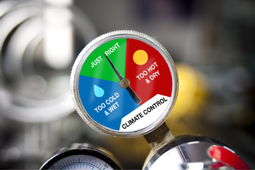 Climate controlled typically means 65 to 85 degrees F with no changes in temperature of more than 10 degrees in one hour. Humidly should be less than 60 percent and often less than 50 percent. Note that pump parts stored below 65 F will not normally be an issue if other parameters are controlled.
There are also Specific Cautions and Procedures for
Rotors, Bearings, Greases, and Seals – Oh My!
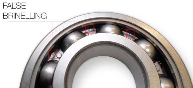
For instance, pump rotating assemblies should be turned by hand every month or two and left in a different position than found to prevent rotor bowing and false brinelling (bearing) issues.
 Note:
Note:
False brinelling can occur simply from small vibrations due to passing traffic and heavy machinery operating nearby.
Sealed for life ball bearings have a 5 year maximum shelve life (due to the grease) even under ideal storage conditions. Mechanical seal assemblies are a detailed combination of metallic and nonmetallic components, which must each follow their own unique preservation regiment.
Ozone:
Exposed (to the atmosphere) rubber products such as spare progressive cavity pump stators and other elastomers are subject to ozone attack. Some elastomers such as EDPM and Viton™ are inherently less prone to ozone issues.
 Procedures:
We have formal engineering procedures to fit most storage situations. We will work with you to make sure the pump and ancillary equipment are stored properly. If you are in a marine, coastal or tropic environment special steps are required even before the pump is shipped.
Postscript:
*The purported shelf life of Twinkies™ …as a millennium, is an urban myth.
-Jim Elsey
Featured, Resources, Summit Pumps

Here are some brief reminders about NPSHA and NPSHR.
NPSH changes with: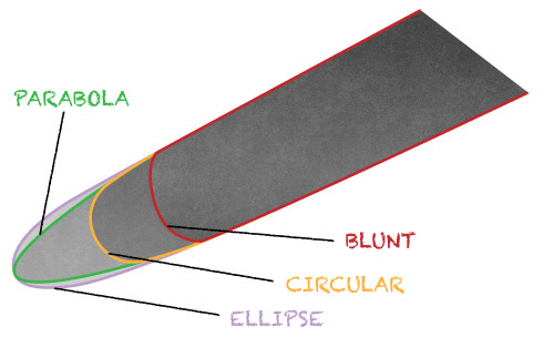
Impeller diameter: For the same flowrate on a given system an impeller of a smaller diameter will have a higher NPSHR.
Clearance of impeller and wear rings: As clearances open up on the pump over time the NPSHR will also increase. This effect is significantly worse for closed impellers than open or semi open styles.
Vane geometry: Specifically the leading edge profile of impeller vanes. The shape of the leading edge will affect NPSHR. Vane geometry in order of best shape to worse shape are 1) parabola 2) ellipse 3) circular 4) blunt.
Speed: Not always 100% true, but for small speed changes NPSHR will vary approximately as the square of the speed ratio for the pump in the midrange operating region and near BEP. For sure, NPSHR increases with speed and vice versa.
Viscosity: Yes an increase in viscosity will increase the NPSHR and decrease the NPSHA. There must be a correction for viscous fluids. In one simple word … friction. See note at bottom for more info.
 Air Entrainment
: Air entrainment in a range of 0.3 to 1.0 percent will actually work to help the NPSH issues, but above 1% the NPSH
R will increase.
Age of system and pump (fouling and corrosion): As systems age and or foul the flow velocity profile and the friction increase. Both factors work to reduce NPSHA and increase NPSHR.
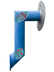 Suction pipe geometry
: For every elbow, twist and turn in the suction pipe the fluid velocity profile becomes turbulent (technical for; it gets all messed up) and creates a mismatch (discrepancy) between the fluid velocity and the impeller inlet vane velocity. This mismatch creates recirculation at the impeller eye that directly affects NPSHR.
NPSH Margins: Last; please understand that pumps with adequate NPSH (calculated) margins…where NPSHA exceeds NPSHR can still cavitate, because the margins are not sufficient and the system dynamics are changing.

Quiz: On your own…see if you understand why the following factors affect NPSH.
- Temperature both ambient and fluid
- Vapor Pressure
- Specific Gravity of the fluid
- Elevation above sea level
Bonus Info:
Pumps require a certain amount of Net Positive Suction Head (NPSH) to operate satisfactorily at a given point of head and flow on the curve to prevent cavitation. These points are empirically determined by the manufacturer (sometimes calculated) and are denoted as Net Positive Suction Head Required (NPSHR).
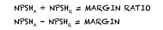
The suction side of the system itself must in return provide a certain amount of NPSH and that is referred to as Net Positive Suction Head Available (NPSHA). There must be more NPSHA than NPSHR for the pump to operate satisfactorily. The difference is referred to as the margin or ratio.
Refer to Hydraulic Institute 9.6.1-2017 for details on margins and ratios.
Viscosity: ANSI/HI Standard 9.6.7- 2015 provides updated instructions for correcting a known water performance into an estimated viscous performance for a given viscosity.
-The Summit Pump Team