Why do most centrifugal pumps fail?
If you ask maintenance and operations, they would say pumps fail due to mechanical seal and bearing issues, and in that order. And throw in the occasional broken shaft to make it more interesting.
The common denominator in most pump failures can be distilled down to shaft deflection caused by excessive radial thrust. Distilled again, the excessive thrust is almost always a direct result of operating the pump outside of the allowable operating region (AOR). Not commonly known or understood is that unbalanced suction loads (nonuniform approach) on the impeller, mismatched profiles (impeller to casing), rotor imbalance and incorrect clearances can also create excessive radial thrust. You may have a different pump failure experience at your facility.
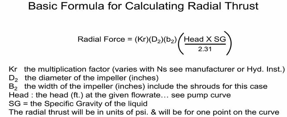 The basic formula for calculating radial thrust in units of pounds per square inch
Regardless of the pump size or type, whenever you operate it, there are always dynamic forces to be managed that are collectively known as the “total dynamic load.” The total dynamic load is the summation of all the forces that manifest throughout the pump as either radial and/or axial loads. There are numerous forces acting at multiple angles and magnitudes relative to the shaft centerline that can be measured through the process of vector analysis. The resultant force that acts at a right angle (normal) to the shaft centerline is the radial force. This right angle force is also frequently called the lateral force.
The pump designer will address these forces by incorporating design features to reduce and/or eliminate the effects. And as with everything in machinery, computer software and real life, there are always compromises to be made. Usually the trade-off is for efficiency and/or reliability.
Radial thrust in a pump is a calculable value. The designer needs to know the value so the forces and subsequent stress levels can be determined. Knowledge of the actual stress levels and forces is required to properly size the shaft and bearings. To calculate the loads, you will need to know the developed head for the specific flow rate you are measuring, along with the liquid’s specific gravity (SG), a multiplier factor (K) and some key impeller dimensions. Note that the magnitude of the thrust will vary with the casing geometry, specific speed (Ns) and the pump’s location (operating point) on the performance curve (see formula). It is important to note that the width of the impeller, also known as the b2 dimension, is always a major factor; the wider the impeller, the higher the thrust. Note that in this case of computing radial thrust, the b2 dimension includes the thickness of the impeller shroud(s), where normally it would not be included.
The magnitude of the radial thrust can also be mitigated by manipulation of the casing/volute geometric design. Resultant shaft deflection caused by the radial thrust can be mitigated by shaft design features and prudent bearing placement.
Shaft Deflection
A perfectly straight pump shaft with no measurable runout that is under stress from radial force can actually bend while in operation, and then later with the pump at rest be again perfectly straight. Since the shaft is rotating and the resultant radial force is pushing on the shaft from only one “resultant direction,” it will cause the shaft to bend (deflect) two times per revolution. The deflections occur at 180 rotating degrees from each other. Consequently, a pump shaft operating at 3,550 rpm will bend (deflect) 7,100 times per minute. To emphasize my point, that would be 426,000 deflections per hour or 3,731,760,000 deflections in a year (yes, 3.7 billion).
Most pump shafts are designed for some degree/level of deflection and cyclic stress, but if your pumps keep breaking shafts, you should resist blaming the manufacturer and stop changing to stronger materials. You can manage reduction of the radial force by operational changes and/or casing and impeller design choices.
Note that if the impeller is out of balance, this will also cause the shaft to deflect. In this case, we refer to this deflection phenomenon specifically as “shaft whip.” Further, if the shaft has a bend in it or if the shaft is sleeved, and there is eccentricity between the two parts, this will also cause “shaft runout” issues.
It is both possible and probable to have all three of these issues occurring at once. That is, simultaneous “shaft whip” due to an unbalanced impeller, “shaft runout” due to a bent shaft, and “shaft deflection” caused by undue radial thrust can all occur at the same time. These are the killers of mechanical seals, bearings and shafts.
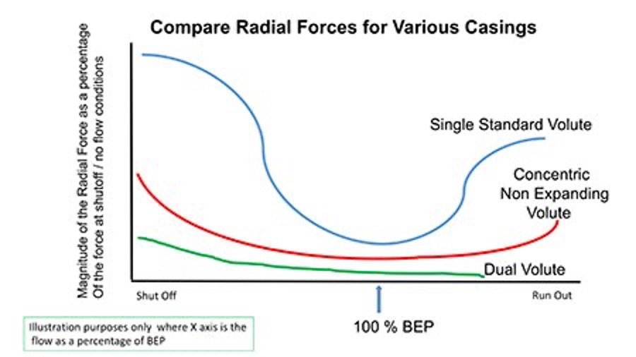 Comparison of radial forces for various casings
How Can I Mitigate Shaft Deflection?
The most important step you can take is to operate the pump in the allowable operating range. If you don’t know where that range is, ask the manufacturer. As a general guideline, 10% or less flow deviation either side of best efficiency point (BEP) is ideal, while 30% under and 15% over would be pushing the reliability factor to be less than satisfactory. Shaft deflection is at its lowest point when the pump is operated at or near its BEP. Operating at BEP is not always possible for many reasons, ranging from an incorrect system curve calculation, the initial pump selection being incorrect, or the system curve or operational requirements having changed since inception of the system design.
For overhung end suction pumps, investigate the pump shaft rigidity factor also known as the “L over D” ratio. Technically this is the L3/D4 ratio of the shaft, where D is the diameter of the shaft in the section between the radial bearing and the impeller centerline, and the L is the distance (length) from the radial bearing to the impeller centerline. It is not the intent of this column to expand on deriving or defining this ratio, but a few comments are necessary. The ratio is derived from the classic cantilevered beam deflection formulas used in basic mechanical engineering statics and dynamics courses. Because it is a ratio, there are no units. Think of this ratio like golf scores—that is, the lower the ratio the better. For the same pump size and model, a solid shaft (lower L over D ratio) would be a better choice than a sleeved shaft. This is not an option if you are operating a packed pump or using component-type seals. Most manufacturers of ANSI B73.1 pumps will, as an option, offer more robust shafts in the middle range of power frames.
Volute: A Critical Component
The pump volute earns its name due to the spiral shape casing surrounding the impeller. The volute is the often forgotten, but nevertheless still critical, component in the pump. Not all volute designs are the same. The volute acts as a collection and pressure containment vessel for the liquid exiting the impeller. The casing also conveniently directs the liquid to the discharge flange. The pump’s magic occurs during this process where the liquid’s velocity energy imparted by the impeller is converted to pressure energy in the volute. Note that the volute plays no part in the generation of the head as that is accomplished solely by the impeller.
From thermodynamics and the first law regarding conservation of energy: energy can neither be created nor destroyed, but it can be altered/changed in form. We can discuss if it is Bernoulli’s equation or Euler’s formula, but let’s agree the velocity energy of the liquid is changed to pressure energy in the volute.
An ideal volute in operation would have a profile of constant velocity around its circumference and at flow rates near the pump design point (aka, BEP). The constant velocity also yields a pressure equilibrium around the volute. However, as the flow rate departs from BEP in either direction (more or less flow), the resulting pressure increases in magnitude and the radial force.
Single Volute
Almost all single-stage centrifugal pumps with nominal casing diameters at or below 12 inches (30.5 centimeters) will be of a single volute design. Different manufacturers may make this key decision at larger or smaller sizes.
Given a pump with a single volute design (one passageway and one cutwater or “tongue”), as you operate away from BEP in either direction, the resultant radial forces will increase exponentially. If you move toward shutoff (lower flows), the resultant force will manifest in one direction at a point 240 degrees from the cutwater. If you move farther out on the curve toward runout (more flow), the resultant force reverses its direction and will manifest at 180 degrees from that first point—that is at 60 degrees from the cutwater. You can use this information when inspecting for root causes of pump failure.
Dual Volute (aka, Twin Volute)
Once a pump casing increases in size to more than 12 inches in diameter (nominal), the dynamic radial forces need to be addressed by means other than simply larger shafts and bigger bearings (an oversimplification). This is accomplished by adding a second cutwater (tongue) and, hence, a second and separate passage, which also provides a separate stream of flow to the volute at 180 degrees from the first one. The addition of the second volute reduces the radial force significantly. The dual volute design is not perfect because the length of the channels (passages) from each cutwater edge to the pump discharge flange are, out of necessity, notably different lengths.
Diffusers
Centrifugal pumps with diffusers placed in the casing were fairly common years ago, especially on multiple-stage pumps. If you are not familiar with diffuser-style pumps, it is easy just to think of them as a higher number of volutes and cutwaters. It is not uncommon to have nine or 10 channels in a diffuser.
Diffusers will greatly reduce the level of radial thrust at almost all flow rates across the curve. There is a small trade-off to efficiency as the added number of diverting edges (cutwaters), along with the additional friction in the numerous channels, presents a parasitic load.
In the last 50 years, industrial markets have traded this reduction in radial forces, and consequently the reliability of diffuser pumps, for the lower initial cost of volute pumps. A diffuser pump will be more expensive for the otherwise same pump in a volute design because the diffusers are castings and difficult to manufacture.
In the present day, diffuser pumps are used in high-energy applications such as in power plant boiler feed and in multistage API 610 refinery and distillation services. Diffuser-style vanes are still frequently used in vertical turbine pump designs.
Special Casings
The single and double volutes share a geometry where the center of the volute is offset from the center of the impeller. Consequently, the corresponding flow path is the shape of a divergent nozzle. A volute starts as a small passage (annulus) and consistently increases in cross-sectional area until it reaches a maximum cross-sectional area at the discharge flange. This design makes for a more efficient pump, but it can result in high radial thrust loads when the flow rate departs from either side of BEP.
Sometimes you need a pump that can handle low flows, but maintain the high head for critical process reasons. For example, you may need 700 to 850 feet of head, but only a 50 gallons per minute (gpm) flow rate. This application would kill the same size pump in a standard volute design. Most manufacturers will offer pumps that have concentric volutes that make this high-head, low-flow condition possible without killing the pump, or as you now know it, death by radial thrust. The trade-off is reduced efficiency and higher noise levels. The advantage is reliability.
The concentric volute, also known as a nonexpanding volute, has its centerline congruent to the impeller centerline; consequently, the annulus (fluid passageway) around the impeller is consistent in its cross-sectional area. The impeller design will be different in that it will have radial vanes of high solidarity and a low specific speed.
If you are experiencing frequent pump problems and can’t figure out why, perhaps radial thrust may be the issue. Please first make sure the suction and discharge valves are open before you jump to conclusions.
-Jim Elsey