Featured
The most tremendous of all earthly events took place almost 2000 years ago when Jesus of Nazareth, put to death by the cruel power of Rome, rose from His tomb and appeared again to His sorrowing followers. With their despair turned to joy, they were inspired to carry His spirit and His teachings to the ends of the earth.
That was the first and greatest Easter experience. But Easter experiences have been happening ever since. They happen every day. They can happen to me and they can happen to you.
Sometimes they are small, gentle moments of reawakening. It is no accident, I’m sure, that Easter comes in the radiant season of rebirth after the bleakness of winter. Each year I walk around my farm on Quaker Hill in Pawling, New York, and thrill to the sound of returning birds. I find myself tingling to the touch of the warm sun and the odor of new young grass.
I marvel at the thought that no one but God knows the process that makes the grass so green. I meditate on the miraculous profusion of spring flowers in their infinite form and color and variety. When I think of old friends and become aware of wonderful qualities I never appreciated before, they too seem to blossom out in a personal springtime.
The Easter experience can also happen to people who are discouraged or defeated, who are groping their way through life burdened by problems and only half-alive, who have lost their sense of wonder, their capacity to be deeply moved, their ability to love and hope and dream. Time and again I have seen the power of the risen Lord reach out and enfold and awaken such people—people entombed by the power of alcohol or drugs, people enslaved by immorality, people who suffer from lost love, lost faith, lost hope—who then rebound, victorious and whole, from their dark night of the soul. When that happens, when the spirit of Easter really touches them, they too come back from the dead.
But the deepest message of Easter now is, and always has been, the promise that this life here on earth is only a beginning for all of us, that the here and the hereafter are merely different aspects of the same thing. “Because I live,” said Jesus, “ye shall live also.” (John 14:19) I take that tremendous promise to mean that eternity does not begin with death; we are living in it now. Death is but a change; a change for the better, that’s all.
This Easter message can reach the human heart in many ways. Not long ago Inez Lowdermilk, wife of the famous conservationist Dr. Walter C.Lowdermilk, shared such an experience with us here at Guideposts. She told how over 40 years ago her husband came upon three yucca plants that had been uprooted and left by bulldozers alongside a new mountain road. He brought them home and rooted them in his Berkeley, California, rock garden.
Within a couple of years, Mrs. Lowdermilk said, two of the yuccas bloomed and died according to their normal life cycle. The other plant did nothing but sit in the rock garden, protected by its circle of needlelike spears.
Walter Lowdermilk went on to become an international authority on forestry, and soil and water conservation, especially famous for his plan for the useful distribution of the waters of the Jordan River in the Holy Land. Last spring he became ill, and one day, 42 years after the rescue of the uprooted yucca plants, his doctor told the family that Waiter’s life was coming to a close.
Soon after, a stalk appeared above the spiny base of the long-dormant yucca. It continued to grow as Waiter’s life ebbed away. Everyone who entered the house watched the stalk grow almost a foot a day until it was over 15 feet tall. On the day that Walter died, it burst into magnificent blossoms, a glorious natural candle made of hundreds of little branches dripping with masses of small ivory-colored bells. The beauty of this masterpiece of nature continued for an entire month. What does this lovely and gentle story have to say to us? We are here on earth for a short time. God wants us to accept His plan for our lives, to develop our talents and make the fullest, most selfless, most constructive use of them. And finally, when our work here is done, we will be taken home, like the yucca that waited until the time was ripe—and then burst into glorious bloom.
Featured, Resources, Summit Pumps

This month, we review the reasoning for multiple pump alignments
and why there may actually be more required than you think!
At the factory… the motor is positioned on the base plate and checked for proper alignment to the pump. As soon as the unit (base/motor/pump) is loaded on the truck the alignment integrity is lost. Later the unit is moved from the truck or warehouse/staging area to the foundation, consequently any semblance of an acceptable alignment tolerance is placed in jeopardy.
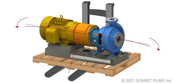
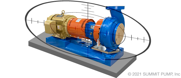
Industry best practices (experienced engineers, millwrights, and rotating equipment experts) will tell you that a pump requires a minimum of at least four (4) alignment checks prior to startup/commissioning. There may be an additional 4 or 5 checks to be conducted in the full commissioning process for a possible total of nine (9).
Align the Pump 9 Times
When I tell people that they need to conduct 9 alignment checks in the process of pump commissioning, I receive a wide range of interesting comments…please first let me explain my statement.
One… the first alignment
As mentioned above; prior to shipment the pump is positioned on the base and centered within its bolt tolerance. The motor is then placed on the base and a “rough alignment” is conducted to ensure that a precision alignment is possible and can be successfully conducted later in the field.
There can be exceptions to this example, and it depends on the type and size of driver. The initial factory alignment may only cover the side-to-side adjustments and not the aspects of the vertical or angular offsets, as those will be addressed in the field. No matter how precise the alignment conducted at the factory and how carefully the equipment is transported … the alignment will change in the process.
Second alignment check
When the pump, motor and base are received at the site and initially set on the foundation the second alignment should be conducted to correct for changes in transit. It is critical that the second alignment be conducted prior to grouting or connecting the piping to the pump. Omitting this step is a common and expensive mistake.
Three… the third alignment
You may have thought you had the alignment completed before, but now that the base is grouted you will find that that the alignment has again moved out of specification.
The process of grouting the base will oftentimes warp or otherwise move the base and offset the alignment. During the grout curing process there is a large amount of heat and some expansion force involved that will potentially change the alignment.
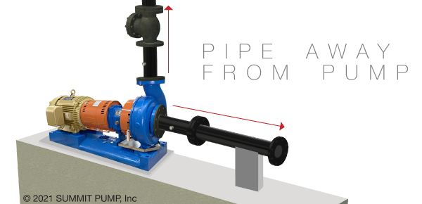
Four… the fourth alignment
Now that the base is properly grouted and the driver is aligned to the pump, it is time to connect the piping to the pump. It is always better to “pipe away” from the pump and not from the system to the pump to avoid unwanted moments and forces. Done correctly, connecting the piping to the pump should not alter the alignment in any way. However, from my experience this is a common reason for the alignment to change out of specification and introduce unwanted stresses into the pump.
Alignment steps 5 thru 9
Involve further preventative measures, double-checking and troubleshooting. If you are experiencing issues with alignment procedures and achieving acceptable results in the field, it could be from omitting key steps in the process.Still interested in correctly conducting alignments and commissioning procedures? Please review my articles on this subject for more information regarding the remaining steps by clicking the links below.
-Jim Elsey
Featured, Resources, Summit Pumps
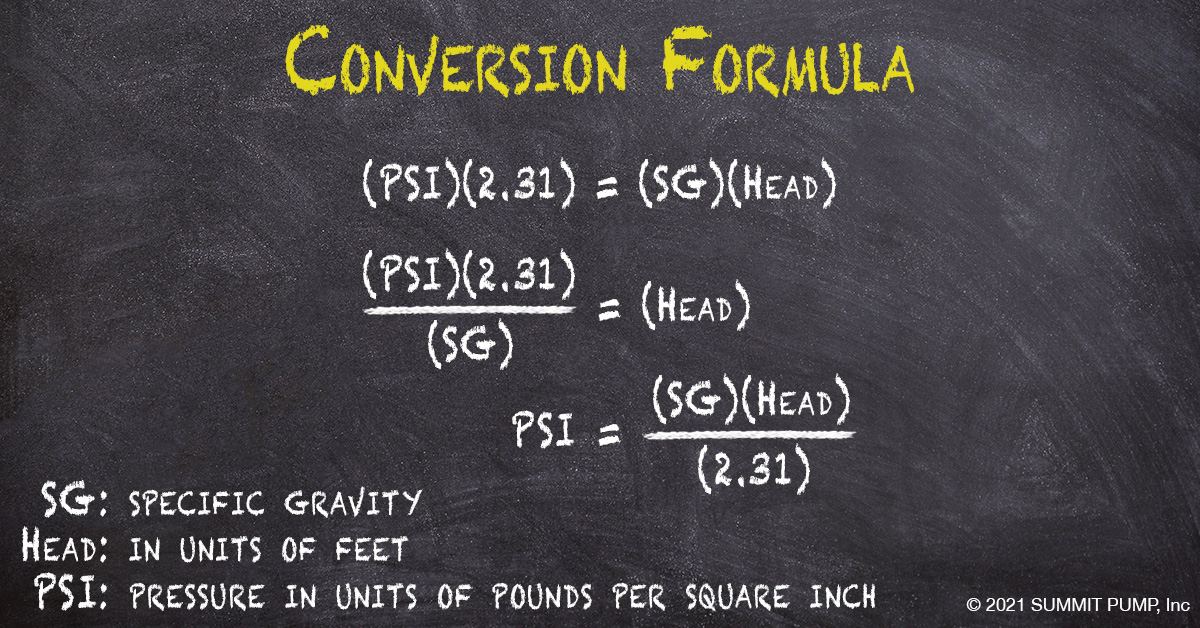
Understanding your suction pressure and knowing how to read a vacuum is critical in identifying performance issues. In the field, instruments measure in units of PSI …whether gauge, absolute or vacuum. When diagnosing issues, PSI must be converted to head in order to calculate Total Dynamic Head (TDH).
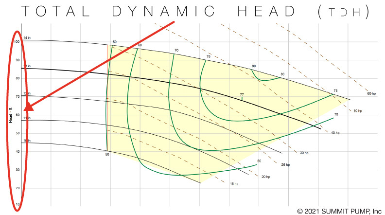
Total Dynamic Head
Consider Total Dynamic Head as the amount of energy the pump converts from suction to discharge. This information is critical in identifying where the pump operates on the performance curve.
Suction Pressure
To illustrate reading vacuum or pressure on the suction side of the pump, we will examine both a flooded suction and a suction lift application. Each example will assume the same pump, the same liquid and the same operation speed. The differential pressure of the pump will be the same for each example.
Note: For simplicity, we will not convert pressure readings to head in these examples, but understand the conversion mentioned above must be done in order to calculate TDH. For a more in-depth explanation, see my full article on the topic.
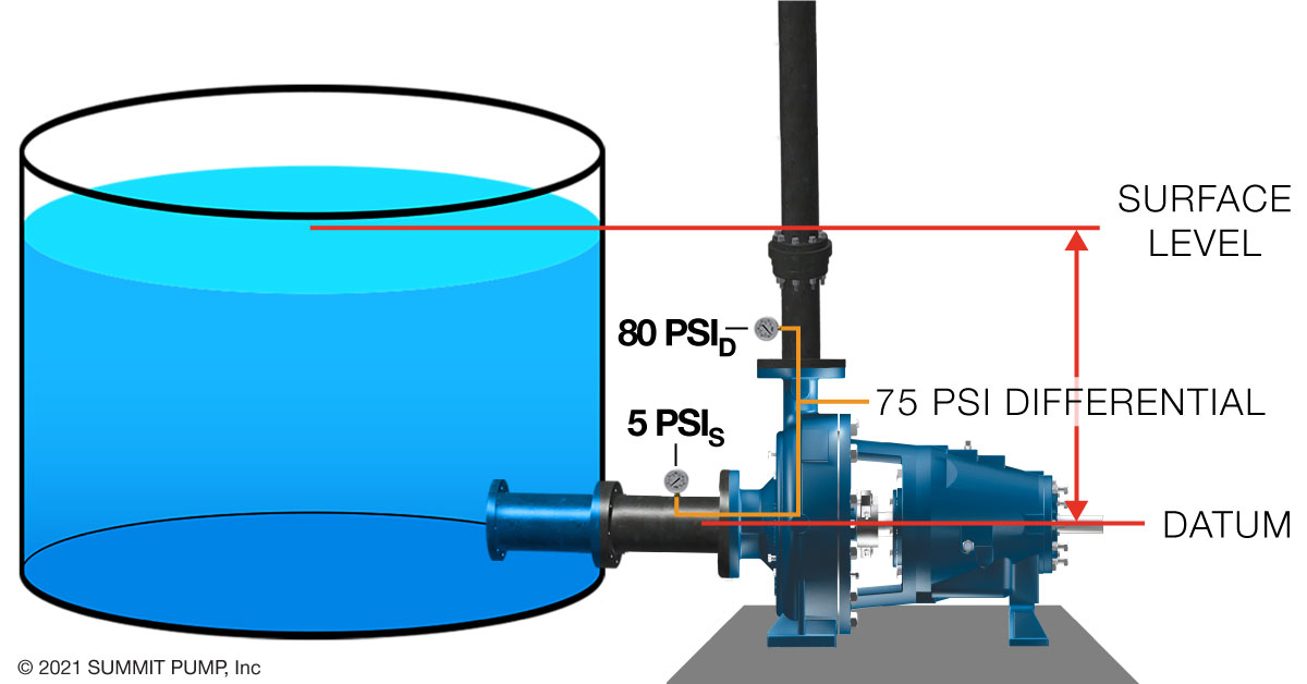
Flooded Suction
In flooded suction, the liquid level is above the pump datum and has energy to provide to the pump. Meaning the pump does not need to convert this energy and will use this “given” energy elsewhere. In this case, a higher discharge pressure.
Suction Lift
In Suction Lift, the pump must generate a low enough pressure at the eye of the impeller to have the fluid pushed into the pump by atmospheric pressure. Energy is used to make this happen and results in less energy available for pressure at the discharge.
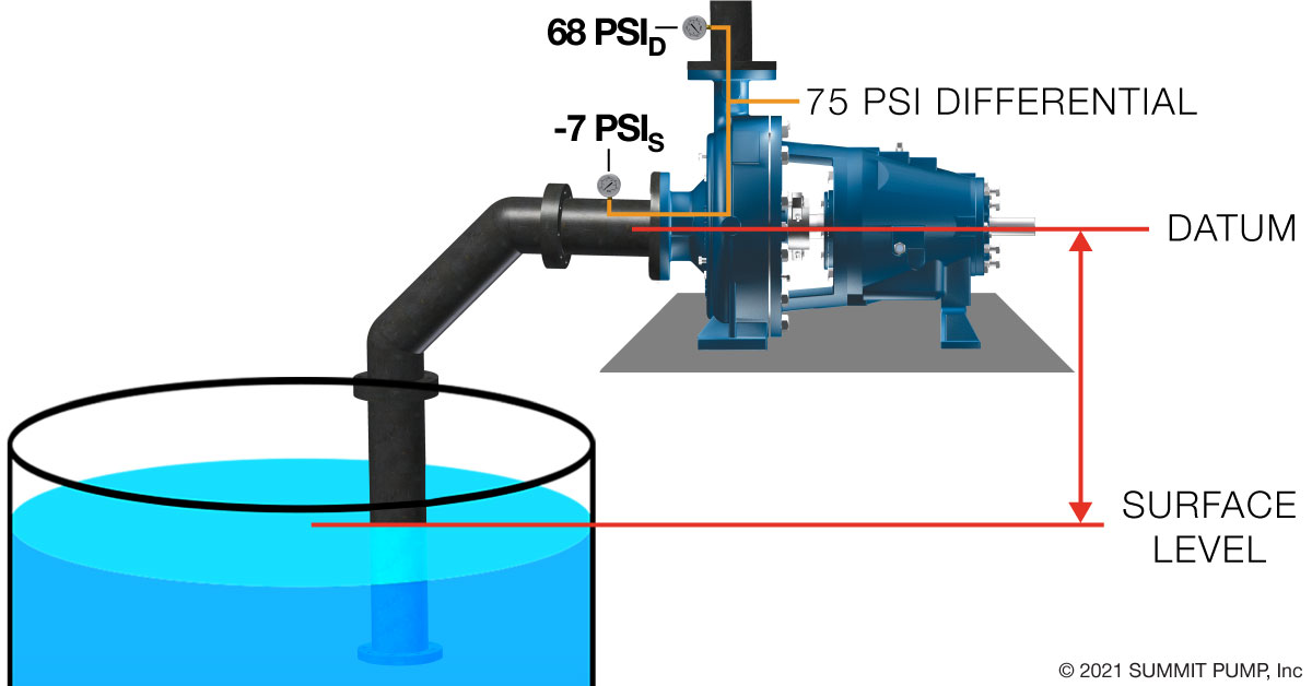
Notice the overall pressure readings are lower but the differential pressure (75 PSI) remains about the same in both flooded and suction lift applications (using the assumptions we made earlier).
Take-a-ways
Pressure gauges neglect velocity energy and read only one type of energy, which is pressure.Understanding your suction pressure and knowing how to read a vacuum is critical in calculating the pump’s TDH (Total Dynamic Head). Knowing the TDH can lead you to resolving several issues including operation cost, safety, pump life, inaccuracy or just nuisance issues.
-Jim Elsey
Featured, Resources, Summit Pumps
Why do most centrifugal pumps fail?
If you ask maintenance and operations, they would say pumps fail due to mechanical seal and bearing issues, and in that order. And throw in the occasional broken shaft to make it more interesting.
The common denominator in most pump failures can be distilled down to shaft deflection caused by excessive radial thrust. Distilled again, the excessive thrust is almost always a direct result of operating the pump outside of the allowable operating region (AOR). Not commonly known or understood is that unbalanced suction loads (nonuniform approach) on the impeller, mismatched profiles (impeller to casing), rotor imbalance and incorrect clearances can also create excessive radial thrust. You may have a different pump failure experience at your facility.
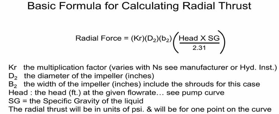 The basic formula for calculating radial thrust in units of pounds per square inch
Regardless of the pump size or type, whenever you operate it, there are always dynamic forces to be managed that are collectively known as the “total dynamic load.” The total dynamic load is the summation of all the forces that manifest throughout the pump as either radial and/or axial loads. There are numerous forces acting at multiple angles and magnitudes relative to the shaft centerline that can be measured through the process of vector analysis. The resultant force that acts at a right angle (normal) to the shaft centerline is the radial force. This right angle force is also frequently called the lateral force.
The pump designer will address these forces by incorporating design features to reduce and/or eliminate the effects. And as with everything in machinery, computer software and real life, there are always compromises to be made. Usually the trade-off is for efficiency and/or reliability.
Radial thrust in a pump is a calculable value. The designer needs to know the value so the forces and subsequent stress levels can be determined. Knowledge of the actual stress levels and forces is required to properly size the shaft and bearings. To calculate the loads, you will need to know the developed head for the specific flow rate you are measuring, along with the liquid’s specific gravity (SG), a multiplier factor (K) and some key impeller dimensions. Note that the magnitude of the thrust will vary with the casing geometry, specific speed (Ns) and the pump’s location (operating point) on the performance curve (see formula). It is important to note that the width of the impeller, also known as the b2 dimension, is always a major factor; the wider the impeller, the higher the thrust. Note that in this case of computing radial thrust, the b2 dimension includes the thickness of the impeller shroud(s), where normally it would not be included.
The magnitude of the radial thrust can also be mitigated by manipulation of the casing/volute geometric design. Resultant shaft deflection caused by the radial thrust can be mitigated by shaft design features and prudent bearing placement.
Shaft Deflection
A perfectly straight pump shaft with no measurable runout that is under stress from radial force can actually bend while in operation, and then later with the pump at rest be again perfectly straight. Since the shaft is rotating and the resultant radial force is pushing on the shaft from only one “resultant direction,” it will cause the shaft to bend (deflect) two times per revolution. The deflections occur at 180 rotating degrees from each other. Consequently, a pump shaft operating at 3,550 rpm will bend (deflect) 7,100 times per minute. To emphasize my point, that would be 426,000 deflections per hour or 3,731,760,000 deflections in a year (yes, 3.7 billion).
Most pump shafts are designed for some degree/level of deflection and cyclic stress, but if your pumps keep breaking shafts, you should resist blaming the manufacturer and stop changing to stronger materials. You can manage reduction of the radial force by operational changes and/or casing and impeller design choices.
Note that if the impeller is out of balance, this will also cause the shaft to deflect. In this case, we refer to this deflection phenomenon specifically as “shaft whip.” Further, if the shaft has a bend in it or if the shaft is sleeved, and there is eccentricity between the two parts, this will also cause “shaft runout” issues.
It is both possible and probable to have all three of these issues occurring at once. That is, simultaneous “shaft whip” due to an unbalanced impeller, “shaft runout” due to a bent shaft, and “shaft deflection” caused by undue radial thrust can all occur at the same time. These are the killers of mechanical seals, bearings and shafts.
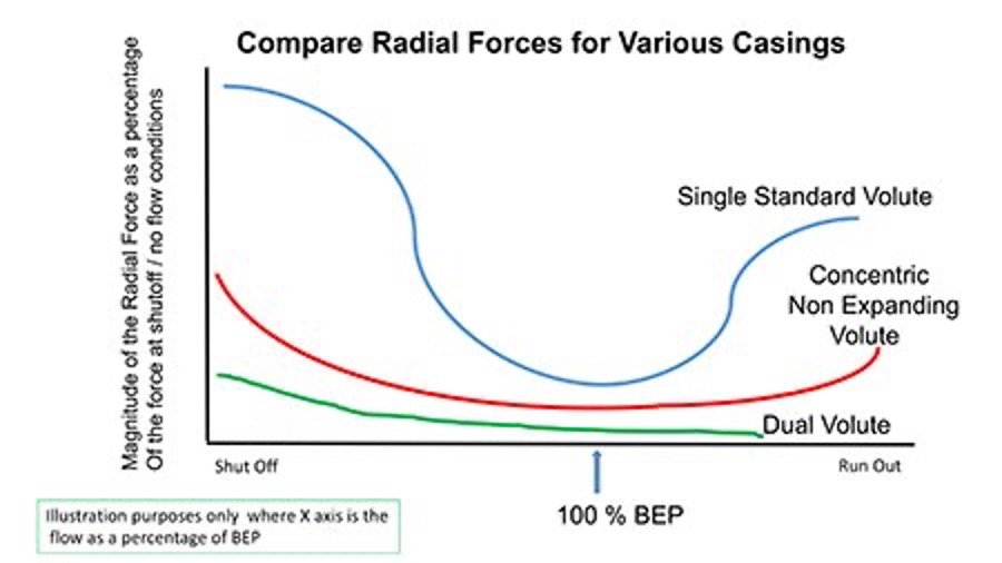 Comparison of radial forces for various casings
How Can I Mitigate Shaft Deflection?
The most important step you can take is to operate the pump in the allowable operating range. If you don’t know where that range is, ask the manufacturer. As a general guideline, 10% or less flow deviation either side of best efficiency point (BEP) is ideal, while 30% under and 15% over would be pushing the reliability factor to be less than satisfactory. Shaft deflection is at its lowest point when the pump is operated at or near its BEP. Operating at BEP is not always possible for many reasons, ranging from an incorrect system curve calculation, the initial pump selection being incorrect, or the system curve or operational requirements having changed since inception of the system design.
For overhung end suction pumps, investigate the pump shaft rigidity factor also known as the “L over D” ratio. Technically this is the L3/D4 ratio of the shaft, where D is the diameter of the shaft in the section between the radial bearing and the impeller centerline, and the L is the distance (length) from the radial bearing to the impeller centerline. It is not the intent of this column to expand on deriving or defining this ratio, but a few comments are necessary. The ratio is derived from the classic cantilevered beam deflection formulas used in basic mechanical engineering statics and dynamics courses. Because it is a ratio, there are no units. Think of this ratio like golf scores—that is, the lower the ratio the better. For the same pump size and model, a solid shaft (lower L over D ratio) would be a better choice than a sleeved shaft. This is not an option if you are operating a packed pump or using component-type seals. Most manufacturers of ANSI B73.1 pumps will, as an option, offer more robust shafts in the middle range of power frames.
Volute: A Critical Component
The pump volute earns its name due to the spiral shape casing surrounding the impeller. The volute is the often forgotten, but nevertheless still critical, component in the pump. Not all volute designs are the same. The volute acts as a collection and pressure containment vessel for the liquid exiting the impeller. The casing also conveniently directs the liquid to the discharge flange. The pump’s magic occurs during this process where the liquid’s velocity energy imparted by the impeller is converted to pressure energy in the volute. Note that the volute plays no part in the generation of the head as that is accomplished solely by the impeller.
From thermodynamics and the first law regarding conservation of energy: energy can neither be created nor destroyed, but it can be altered/changed in form. We can discuss if it is Bernoulli’s equation or Euler’s formula, but let’s agree the velocity energy of the liquid is changed to pressure energy in the volute.
An ideal volute in operation would have a profile of constant velocity around its circumference and at flow rates near the pump design point (aka, BEP). The constant velocity also yields a pressure equilibrium around the volute. However, as the flow rate departs from BEP in either direction (more or less flow), the resulting pressure increases in magnitude and the radial force.
Single Volute
Almost all single-stage centrifugal pumps with nominal casing diameters at or below 12 inches (30.5 centimeters) will be of a single volute design. Different manufacturers may make this key decision at larger or smaller sizes.
Given a pump with a single volute design (one passageway and one cutwater or “tongue”), as you operate away from BEP in either direction, the resultant radial forces will increase exponentially. If you move toward shutoff (lower flows), the resultant force will manifest in one direction at a point 240 degrees from the cutwater. If you move farther out on the curve toward runout (more flow), the resultant force reverses its direction and will manifest at 180 degrees from that first point—that is at 60 degrees from the cutwater. You can use this information when inspecting for root causes of pump failure.
Dual Volute (aka, Twin Volute)
Once a pump casing increases in size to more than 12 inches in diameter (nominal), the dynamic radial forces need to be addressed by means other than simply larger shafts and bigger bearings (an oversimplification). This is accomplished by adding a second cutwater (tongue) and, hence, a second and separate passage, which also provides a separate stream of flow to the volute at 180 degrees from the first one. The addition of the second volute reduces the radial force significantly. The dual volute design is not perfect because the length of the channels (passages) from each cutwater edge to the pump discharge flange are, out of necessity, notably different lengths.
Diffusers
Centrifugal pumps with diffusers placed in the casing were fairly common years ago, especially on multiple-stage pumps. If you are not familiar with diffuser-style pumps, it is easy just to think of them as a higher number of volutes and cutwaters. It is not uncommon to have nine or 10 channels in a diffuser.
Diffusers will greatly reduce the level of radial thrust at almost all flow rates across the curve. There is a small trade-off to efficiency as the added number of diverting edges (cutwaters), along with the additional friction in the numerous channels, presents a parasitic load.
In the last 50 years, industrial markets have traded this reduction in radial forces, and consequently the reliability of diffuser pumps, for the lower initial cost of volute pumps. A diffuser pump will be more expensive for the otherwise same pump in a volute design because the diffusers are castings and difficult to manufacture.
In the present day, diffuser pumps are used in high-energy applications such as in power plant boiler feed and in multistage API 610 refinery and distillation services. Diffuser-style vanes are still frequently used in vertical turbine pump designs.
Special Casings
The single and double volutes share a geometry where the center of the volute is offset from the center of the impeller. Consequently, the corresponding flow path is the shape of a divergent nozzle. A volute starts as a small passage (annulus) and consistently increases in cross-sectional area until it reaches a maximum cross-sectional area at the discharge flange. This design makes for a more efficient pump, but it can result in high radial thrust loads when the flow rate departs from either side of BEP.
Sometimes you need a pump that can handle low flows, but maintain the high head for critical process reasons. For example, you may need 700 to 850 feet of head, but only a 50 gallons per minute (gpm) flow rate. This application would kill the same size pump in a standard volute design. Most manufacturers will offer pumps that have concentric volutes that make this high-head, low-flow condition possible without killing the pump, or as you now know it, death by radial thrust. The trade-off is reduced efficiency and higher noise levels. The advantage is reliability.
The concentric volute, also known as a nonexpanding volute, has its centerline congruent to the impeller centerline; consequently, the annulus (fluid passageway) around the impeller is consistent in its cross-sectional area. The impeller design will be different in that it will have radial vanes of high solidarity and a low specific speed.
If you are experiencing frequent pump problems and can’t figure out why, perhaps radial thrust may be the issue. Please first make sure the suction and discharge valves are open before you jump to conclusions.
-Jim Elsey
Featured, Resources, Summit Pumps
The concept of vacuum mystifies some people when encountered on pump applications. Today, we hope to simplify the problem.
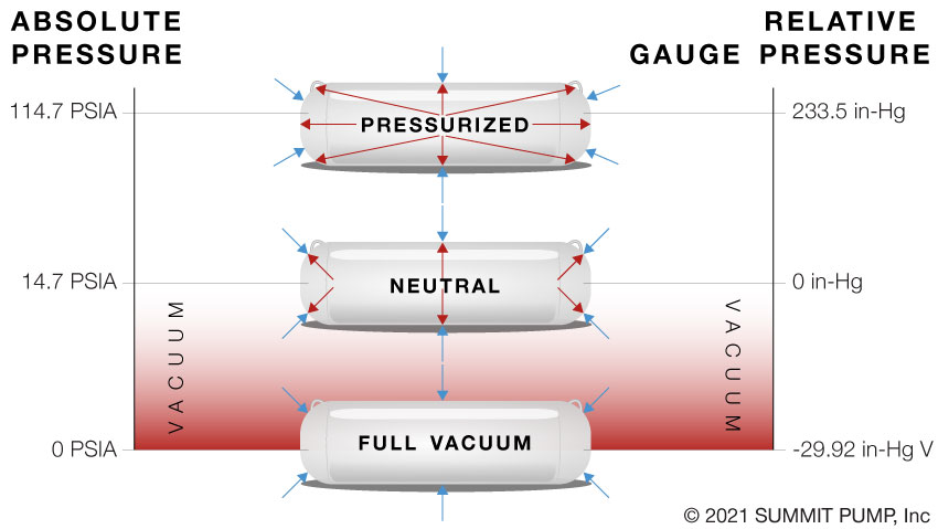
Pressure vs. Vacuum
Even in a vacuum there remains some pressure… it is simply a pressure at a magnitude below the surrounding atmospheric pressure. Vacuum does not necessarily mean the absence of all pressure; vacuum can be any pressure between 0 PSIA and 14.7 PSIA.
As a refresher…we offer the following points:
- Vacuum or vacuum pressure measurements are characterized as either absolute or relative (gauge).
- Absolute pressure is measured from zero, which means a 100% or a perfect vacuum.
- Relative pressure measurements are in reference to the atmospheric pressure. So if you see the word gauge or vacuum in the description it is being measured relative to atmosphere.
- Absolute pressure = gauge pressure + atmospheric pressure.
- Absolute pressure can be zero, but it can never be negative.
- Absolute pressure at sea level is usually given as 14.7 PSIA.
- Atmospheric pressure changes with elevation referenced to sea level and changes with barometric pressure (weather). If you are using gauge pressure to measure pressure or vacuum, you need to state the atmospheric pressure at the time of the measurement.
Units, Scales and Terms
In the pump world we often encounter two descriptive terms, “absolute” and/or “vacuum” assigned to the measurement scale. Further, the measurements may either be in units of inches of Mercury (in-Hg) or pounds per square inch (PSI) in absolute pressure (PSIA) or gauge pressure (PSIG).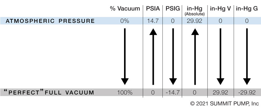
A perfect vacuum, if measured in absolute terms is zero (0 inches Hg) but is 29.92 in-Hg V (-29.92 in-Hg G) if the measured units are deemed relative (vacuum or gauge).
Due to the differences in these two measurement methods you need to ask the equipment owner if the parameter measurement scale is absolute or relative? The methods are 100% opposite of each other and if not properly understood can lead to some big mistakes.
Application
If we had a container at a theoretical perfect vacuum (that is, we have removed every molecule and its components from within the vessel) then we could state that vacuum condition as 0 (zero) pressure absolute or 0 PSIA.
However, if we were to measure our perfect vacuum in inches of Mercury Vacuum or inches Hg V the reading would be 29.92 inches Hg V not zero PSIA as in the first part of the example.
Need More?
Stay tuned for part two in next month’s 60 seconds with Summit Pump for more information.
-Jim Elsey